Method and device for guiding the movement of a moving machine element on a numerically controlled machine

a numerically controlled machine and moving machine technology, applied in the direction of electric controllers, program control, instruments, etc., can solve the problems of not being able to achieve the optimal time and movement profile, and only being able to use s

Active Publication Date: 2012-10-23
SIEMENS AG
View PDF14 Cites 6 Cited by
  • Summary
  • Abstract
  • Description
  • Claims
  • Application Information

AI Technical Summary

Benefits of technology

[0013]The invention is based on the object of providing a simple method and a simple device for guiding the movement of a moving machine element of a numerically controlled machine in which the restriction on the machine axles of the machine is utilized as well as possible.
[0024]Furthermore, it proves advantageous if at at least two connecting points the path acceleration assumes a value of zero.
[0025]In addition, it proves advantageous if at more than two connecting points the path acceleration assumes a value of zero.
[0026]In addition, it proves advantageous if the machine is embodied as a machine tool, production machine and / or as a robot since methods for guiding the movement of moving machine elements are required particularly in these technical fields.
[0027]Furthermore it proves advantageous that the device has means for determining a jolt profile for the guidance of the movement, wherein adjacent path speed segments of two adjacent minimum values are connected to one another, while complying with the maximum possible path jolt and the maximum possible path acceleration, in such a way that in at least one connecting point the path acceleration assumes a value of zero. This constitutes a particularly simple way of connecting the path speed segments to one another and complying with the required condition for the possibility of double continuous differentiation of the path length s over time t.
[0028]In addition, it proves advantageous if the device is embodied as a control device for controlling the machine. If the device is embodied as a control device for controlling the machine no separate control device is required to control the machine.

Problems solved by technology

In this context, according to the prior art it is consciously accepted that the movement profile which is acquired in this way is not optimum with respect to time, i.e. that in particular the maximum possible path acceleration alim(s) and the maximum possible path speed vlim(s) are utilized only inadequately.

Method used


Image

  • Method and device for guiding the movement of a moving machine element on a numerically controlled machine
  • Method and device for guiding the movement of a moving machine element on a numerically controlled machine
  • Method and device for guiding the movement of a moving machine element on a numerically controlled machine

Examples


Embodiment Construction

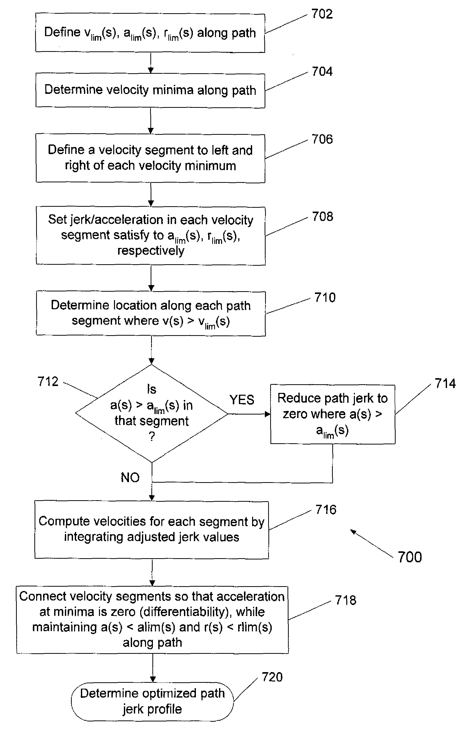
[0039]The inventive method is illustrated in FIG. 5 and FIG. 6. FIG. 7 is a process flow diagram of a process 700 for determining the optimal parameters for the path speed segments according to the invention. The steps listed in the following description of the process refer to FIG. 7.

[0040]In this respect, FIGS. 5 and 6 show the maximum possible path speed vlim(s), the maximum possible path acceleration alim(s) and the maximum possible path jolt rlim(s) which are predefined for the method as limiting values, at step 702, plotted against the path length s. In a method step, the local minimum values of the maximum possible speed vlim(s) are firstly determined. In step 704, the local minimum values are designated in FIG. 5 by M1, M2, M3 and M4. Local minimum values are to be understood here as regions in which the maximum possible speed vlim(s) rises again to the left and to the right of these regions. In this context, the starting point and end point of the maximum possible speed vli...


PUM


Abstract

The invention relates to a method and a device for guiding the movement of a moving machine element on a numerically controlled machine, whereby maximum possible track speed, maximum possible track acceleration, and maximum possible track jerk are defined by means of given restrictions on track axes. The local minima for the maximum possible track speed are determined, whereby for each local minimum a corresponding left-sided and right-sided track speed segment is determined, whereby, for track values for the displacement track to the left and right of a given minimum, the resulting track speed is determined by using the maximum possible track jerk and the maximum possible track acceleration until the track speed exceeds the maximum possible track speed to the left and right of the minimum, a track jerk curve for the movement guidance is hence determined. According to the invention, a simple method and a simple device for movement guidance of a moving machine element on a numerically controlled machine are achieved, with as good as possible a usage of the restrictions on machine axes of the machine.

Description

BACKGROUND OF THE INVENTION[0001]The invention relates to a method and device for guiding the movement of a moving machine element of a numerically controlled machine, wherein a movement path of the machine element is broken up into successive movement sections, wherein a maximum possible path speed, a maximum possible acceleration and a maximum possible path jolt are defined by means of predefined restrictions on machine axles.[0002]FIG. 1 illustrates, in the form of a block circuit diagram, a customarily used electrical drive system of a machine tool, of a production machine and / or of a robot. In the two-axle machine illustrated by way of example in FIG. 1, a controller 1 controls the two machine axles 6a and 6b of the machine. The machine axle 6a is composed here of a regulating system 2a, a converter 3a, a drive motor 4a and a mechanism 5a which is connected to the drive motor 4a. The machine axle 6b is composed of a regulating system 2b, a converter 3b, a drive motor 4b and a m...

Claims


Application Information

Patent Timeline
Patent Type & Authority Patents(United States)
IPC IPC(8): G05B19/29
CPCG05B19/416G05B2219/40519G05B2219/43058G05B2219/43065G05B2219/43203
Inventor HOFFMANN, WALTERPAPIERNIK, WOLFGANGSAUER, TOMAS
Owner SIEMENS AG
Why Eureka
Try Eureka