
Method and device for inspecting defects on both surfaces of magnetic disk

a magnetic disk and defect technology, applied in the field of methods and devices for inspecting the front and back surfaces of magnetic disks, can solve the problems of increasing the numerical aperture by increasing the size of the objective lens, affecting the inspection effect, so as to achieve the effect of high sensitivity without increasing the size of the devi

Active Publication Date: 2012-10-23
HITACHI HIGH-TECH CORP
View PDF8 Cites 14 Cited by
  • Summary
  • Abstract
  • Description
  • Claims
  • Application Information

AI Technical Summary

Benefits of technology

The present invention provides a method and device for inspecting both surfaces of a magnetic disk for defects. The device includes aspherical Fresnel lenses to reduce the size of the system and detect microscopic defects with high sensitivity without increasing the size of the device. The device can be installed in a space that is half or less than that for a conventional inspection device, achieving high cost performance with a high throughput for inspection. The technical effects of the invention include the ability to inspect both surfaces of a magnetic disk simultaneously for defects and detect microscopic defects with high sensitivity.

Problems solved by technology

However, if the intensity of the light emitted is too high, the surface of the substrate may be damaged.
Thus, practically, increasing the size of the numerical aperture by increasing the size of the objective lens has a limit.
It is, therefore, difficult to provide the same optical system (that is used for inspection) on the side of the back surface of the substrate as that provided on the side of the front surface of the substrate, when inspections on both surfaces of a substrate are simultaneously to be performed.
It is, therefore, difficult to reduce the size and weight of the inspection device.
However, since the two inspecting sections are arranged side by side and the reversing mechanism is provided between the two inspecting sections, an area on which to install the inspection system will be large.
However, JP-A-H4-62457 does not describe a structure that uses an optical system having a large numerical aperture on both sides of the disk to detect light scattered from microscopic defects.

Method used


Image

  • Method and device for inspecting defects on both surfaces of magnetic disk
  • Method and device for inspecting defects on both surfaces of magnetic disk
  • Method and device for inspecting defects on both surfaces of magnetic disk

Examples


Embodiment Construction

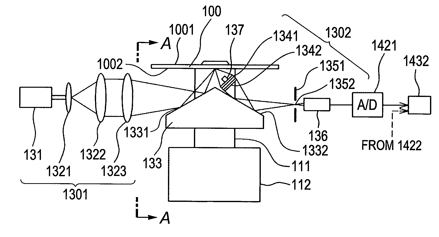
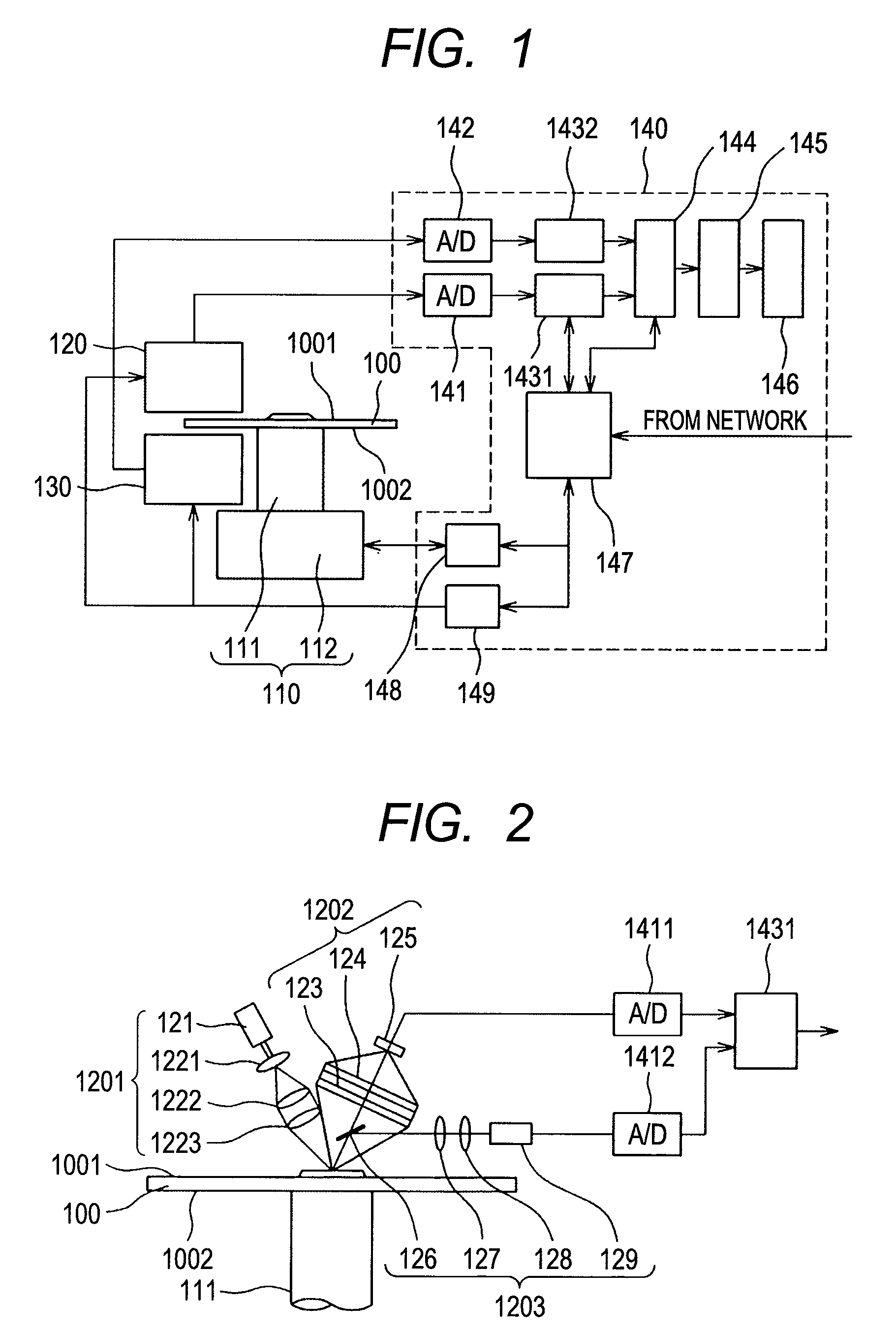
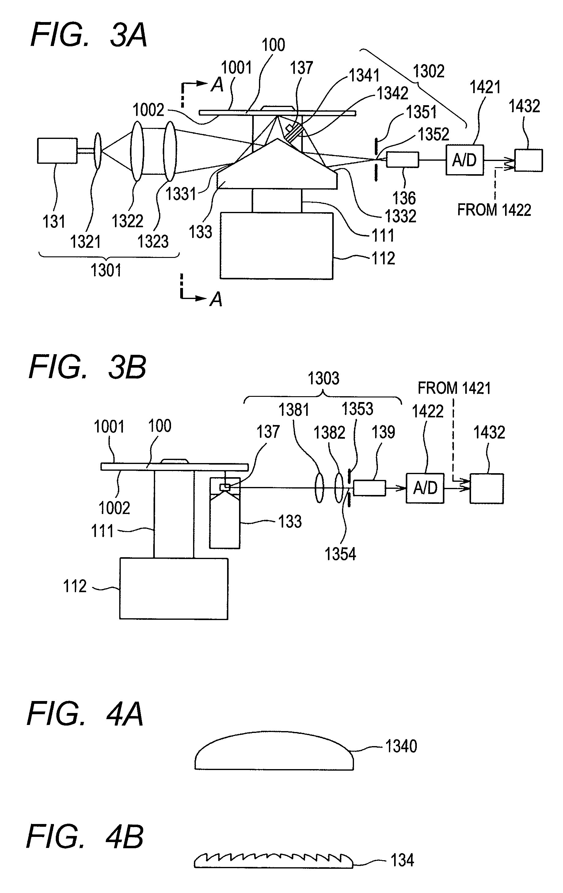
[0036]According to the present invention, an optical system includes an aspherical Fresnel lens and is used instead of a detection optical system having a conventional lens, in order to detect a microscopic defect with high sensitivity. The optical system is included in a structure that simultaneously inspects both surfaces of a sample. The aspherical Fresnel lens allows the optical system to be installed in a relatively narrow space and to have a large numerical aperture.

[0037]In addition, according to the present invention, a device for inspecting both surfaces of a magnetic disk for defects thereon includes: a front-side defect detecting section for optically detecting a scratch and a defect that are present on the front surface of the magnetic disk; and a back-side defect detection section for optically detecting a scratch and a defect that are present on the back surface of the magnetic disk. The back-side defect detecting section includes an optical path changing section. The ...


PUM

PropertyMeasurementUnit
angleaaaaaaaaaa
sizeaaaaaaaaaa
optical pathaaaaaaaaaa

Abstract

A device that is capable of simultaneously inspecting both sides of surfaces of a magnetic disk to detect defects thereon includes a front-side defect detecting section and a back-side defect detecting section each of which optically detect a scratch and a defect that are present on the front and back surfaces of the magnetic disk, to improve a throughput for inspection. The back-side defect detecting section has an optical path changing section that reflects a laser beam emitted by a laser light source to change an optical path thereof and thereby to direct the laser beam toward the back surface of the magnetic disk and that reflects scattered light that has been collected by a Fresnel lens to change an optical path thereof and thereby to direct the scattered light toward a first photoelectric converter.

Description

BACKGROUND OF THE INVENTION[0001]1. Field of the Invention[0002]The present invention relates to a method and device for inspecting front and back surfaces of a magnetic disk for defects thereon. The invention more particularly relates to a method and device for inspecting front and back surfaces of a magnetic disk for defects thereon, which are suitable to optically inspect the front and back surfaces of the magnetic disk simultaneously and thereby to detect a dent and a scratch on the front and back surfaces of substrates of the magnetic disk and detect foreign substances attached to the front and back surfaces of the magnetic disk.[0003]2. Description of the Related Art[0004]A device for optically inspecting a magnetic disk for microscopic defects on surfaces of a substrate thereof is needed to have more enhanced inspection sensitivity and higher throughput for inspection. Schemes of achieving higher throughput for inspection are described in JP-A-H3-186739 and JP-A-H5-21561. Spe...

Claims


Application Information

Patent Timeline
Patent Type & Authority Patents(United States)
IPC IPC(8): G01N21/00
CPCG01N21/95
Inventor USUDA, KATSUTOSHI
Owner HITACHI HIGH-TECH CORP
Learn More