
Method for detecting the position of a closure element in a water distribution mechanism

a technology of closure element and water distribution mechanism, which is applied in the direction of cleaning equipment, process and machine control, instruments, etc., can solve the problems of high complexity of the changeover device and the increase of the cost of producing the dishwasher, and achieve the effect of more economical

Active Publication Date: 2012-10-23
BSH BOSCH & SIEMENS HAUSGERAETE GMBH
View PDF13 Cites 8 Cited by
  • Summary
  • Abstract
  • Description
  • Claims
  • Application Information

AI Technical Summary

Benefits of technology

[0003]The object of the present invention is to disclose a more economical method and a device for detecting the position of a closure element in a changeover device of a dishwasher so that the closure element's position will be detected quickly and reliably after a fault incident.
[0006]The closure element is in contrast to the prior art actively driven in the changeover device by the inventive method. That has the advantage that the closure element's position can be quickly and reliably determined after a fault incident by a defined course of movement. Only the closure element's position within a defined course of movement will for that purpose continue being changed until the reference position has been reached. The closure element can be selectively driven again from the reference position.
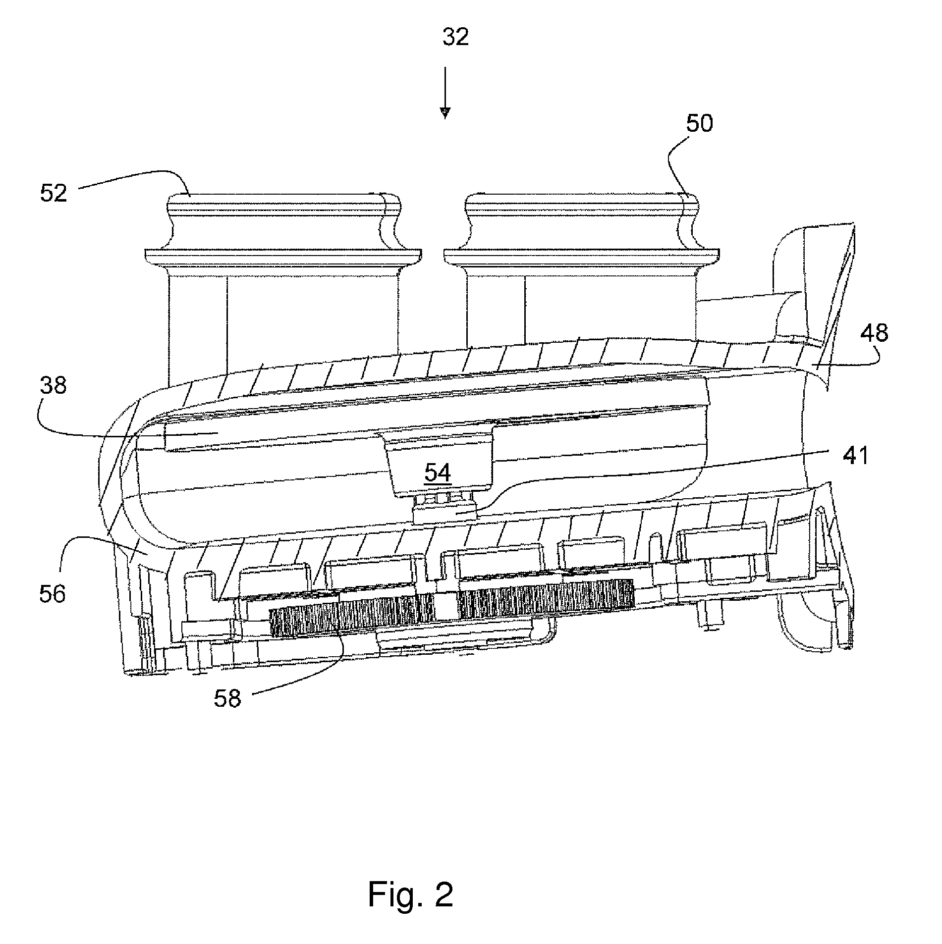
[0007]A further advantage lies in the changeover device's simple structure. All it requires is a housing, having one inlet and various outlets, and a closure element that is moved by a drive device. It is possible to dispense with sensor systems for detecting the position of the closure element, whether they be located directly in the water diverter or, for indirect registering, in the circulating pump. The housing can be, for example, a hollow cylinder in which a discoid closure element is turned by, for instance, an electric motor. Simple geometric shapes or standard parts are economical. Moreover, fewer individual parts will be required overall, as a result of which the assembly effort will be reduced. What is more, the reduction in parts, particularly moving parts, will result in fewer sources of disruption and fewer frictional losses in the changeover device.
[0008]According to an advantageous embodiment variant of the invention, the closure element is stopped in the reference position in order to synchronize its position with the changeover device. That means that the closure element's position will be harmonized with reference elements such as, for example, the outlets on the changeover device's housing. From the reference position the closure element can then again be driven in a defined manner as a function of a program cycle. The reference position preferably corresponds to a position of the closure element, which position is assumed also during a program cycle relative to the changeover device's housing. It is thereby insured that the program cycle can be resumed as soon as possible after a disruptive incident because an additional step of the method for orienting the closure element from the reference position is dispensed with.
[0011]Apart from the current consumption it is basically also possible to ascertain other signal values such as, for instance, rotation speed, pressure, load angle, or vibration on the circulating pump. The circulating pump's current consumption is, through, preferably ascertained by the control device as the signal value during position detecting. Additional sensors in or on the circulating pump can be dispensed with when the current consumption is ascertained as the signal value. The current consumption will in any event be registered by the control device when the circulating pump is being driven as it is used for influencing performance or controlling rotation speed. Additional parts on the circulating pump can be dispensed with, and costs as well as additional sources of faults hence reduced.
[0013]Because characteristics of the circulating pump have to be data-registered in any event for controlling it, the proposed device will necessitate no extra structural effort. Rather it relies on largely existing devices so that it will be more economical compared with an additional sensor system.

Problems solved by technology

What is disadvantageous about that embodiment variant is on the one hand the highly complex structure of the changeover device, because both the outer walls and additional elements inside the changeover device have to insure valve-body guiding.
That results overall in higher costs for producing the dishwasher.

Method used


Image

  • Method for detecting the position of a closure element in a water distribution mechanism
  • Method for detecting the position of a closure element in a water distribution mechanism
  • Method for detecting the position of a closure element in a water distribution mechanism

Examples


Embodiment Construction

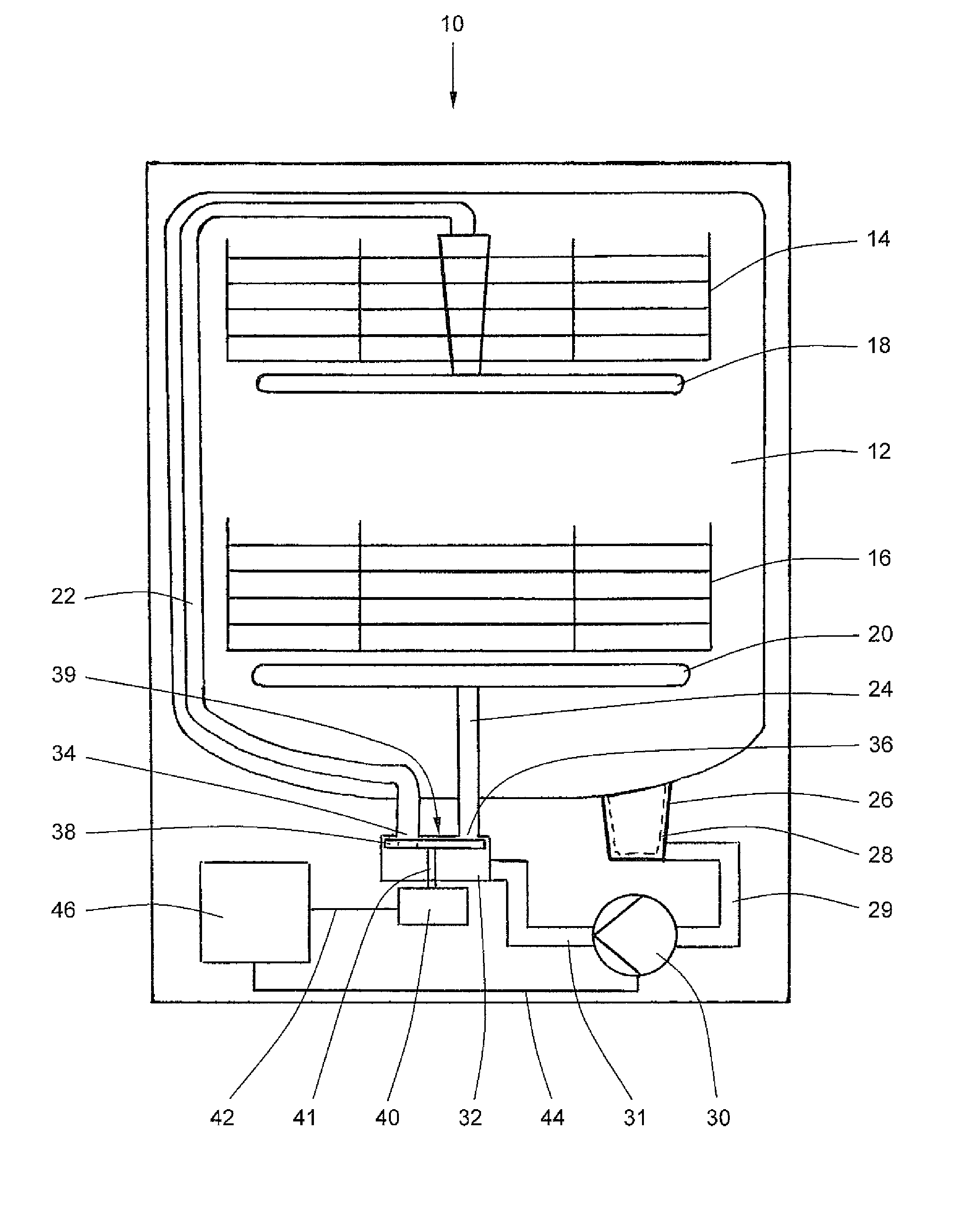
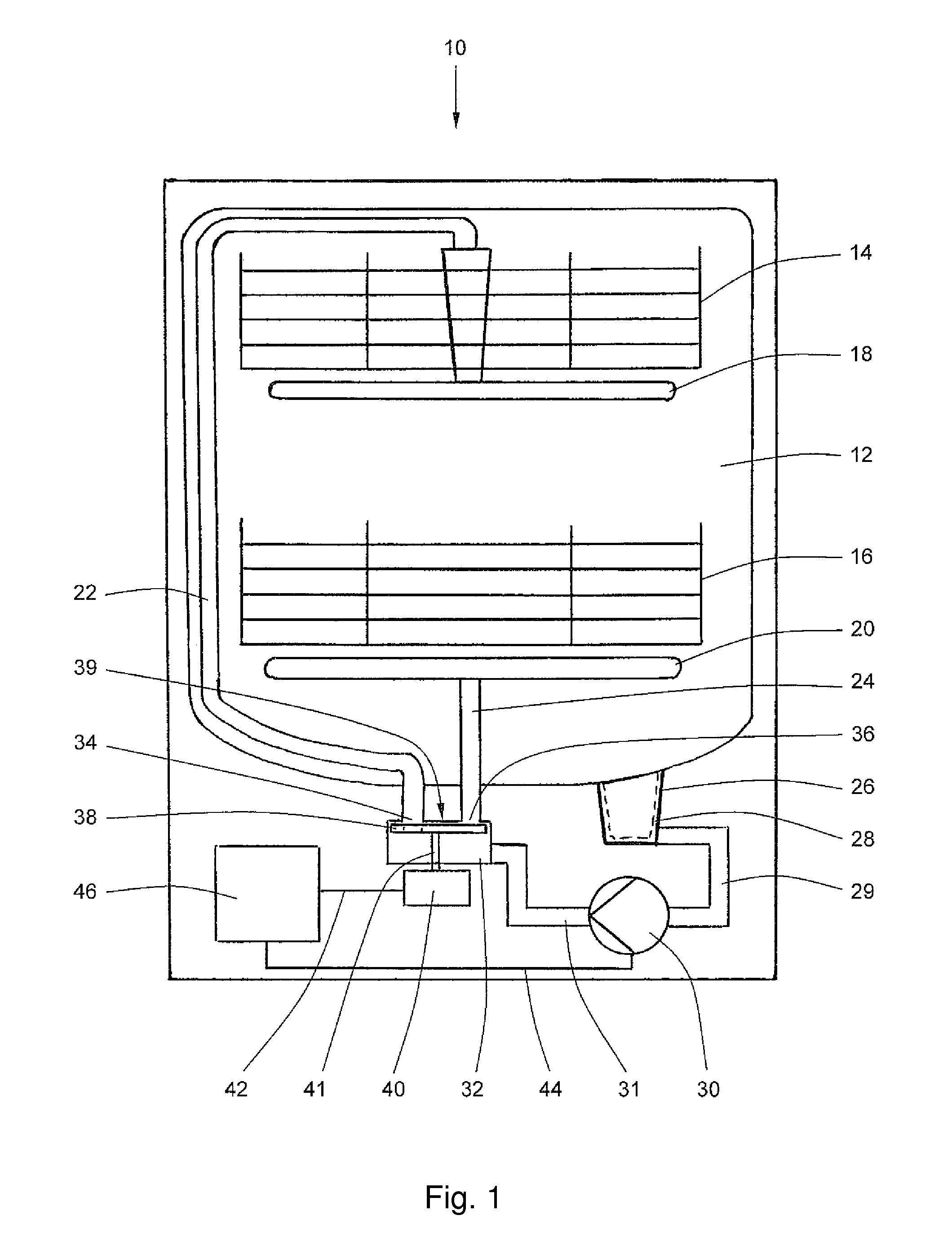
[0018]FIG. 1 is a schematic of a dishwasher 10 having a washing container 12 in which are located an upper basket 14 and a lower basket 16. Mounted rotatably below the upper basket 14 is an upper spraying system 18 and below the lower basket 16 is a lower spraying system 20 each in the form of a spraying arm. The upper spraying system 18 is supplied via a feeder line 22 and the lower spraying system via a feeder line 24 with rinsing fluid. Located below the washing container 12 is a sump 26 having a filter insert 28 that is linked via a fluid line 29 to a circulating pump 30. The circulating pump 30 is connected via a fluid line 31 to a water diverter 32. It has a covering surface 39 having two openings 34, 36, with the opening 34 being linked to the feeder line 22 and the opening 36 to the feeder line 24.

[0019]Mounted rotatably inside the cylindrical water diverter 32 parallel to the covering surface 39 is a discoid closure element 38. It is arranged in a rotationally fixed manner ...


PUM


Abstract

A method and a device are provided for detecting the position of a closure element of a movement reversal device in a dishwasher. The device determines the position of a closure element via a comparison of a value corresponding to a predefined reference position of the closure element with a signal value of a circulation pump of the dishwasher.

Description

BACKGROUND OF THE INVENTION[0001]The present invention relates to a method for detecting the position of a closure element in a changeover device of a dishwasher. The term “water diverter” can be employed synonymously with the term “changeover device”. The function of the changeover device is to distribute a rinsing fluid among various spraying systems or spraying levels inside a washing container of the dishwasher. A circulating pump is used to transport the rinsing fluid. A drive device driven by a control device changes the position of the closure element. The invention relates further to a device for detecting the closure element's position.[0002]A changeover device of said type is known from DE 198 57 101 B4. The closure element's position is detected via a rotation-speed sensor on a circulating pump located in front of the changeover device. Said sensor is linked to an electronic control device that ascertains the valve body's position by way of the pump's rotation speed. Use ...

Claims


Application Information

Patent Timeline
Patent Type & Authority Patents(United States)
IPC IPC(8): G05D11/00
CPCA47L15/0049A47L15/4221A47L15/4225A47L2401/08
Inventor HEISELE, BERNDOBLINGER, ANTONREITER, ANDREASROSENBAUER, MICHAELSEMERAD, DAVIDWOLF, CHRISTIAN
Owner BSH BOSCH & SIEMENS HAUSGERAETE GMBH
Learn More