Modular scalable coolant distribution unit
a distribution unit and modular technology, applied in the field of modular, scalable, coolant distribution units, can solve the problems of inability to meet the demand for cooling, inability to reach the maximum load, unnecessary up-front capital costs and inefficiencies, etc., to achieve low cost, reduce up-front costs, and reduce heat load. the effect of large variation of heat load
- Summary
- Abstract
- Description
- Claims
- Application Information
AI Technical Summary
Benefits of technology
Problems solved by technology
Method used
Image
Examples
first embodiment
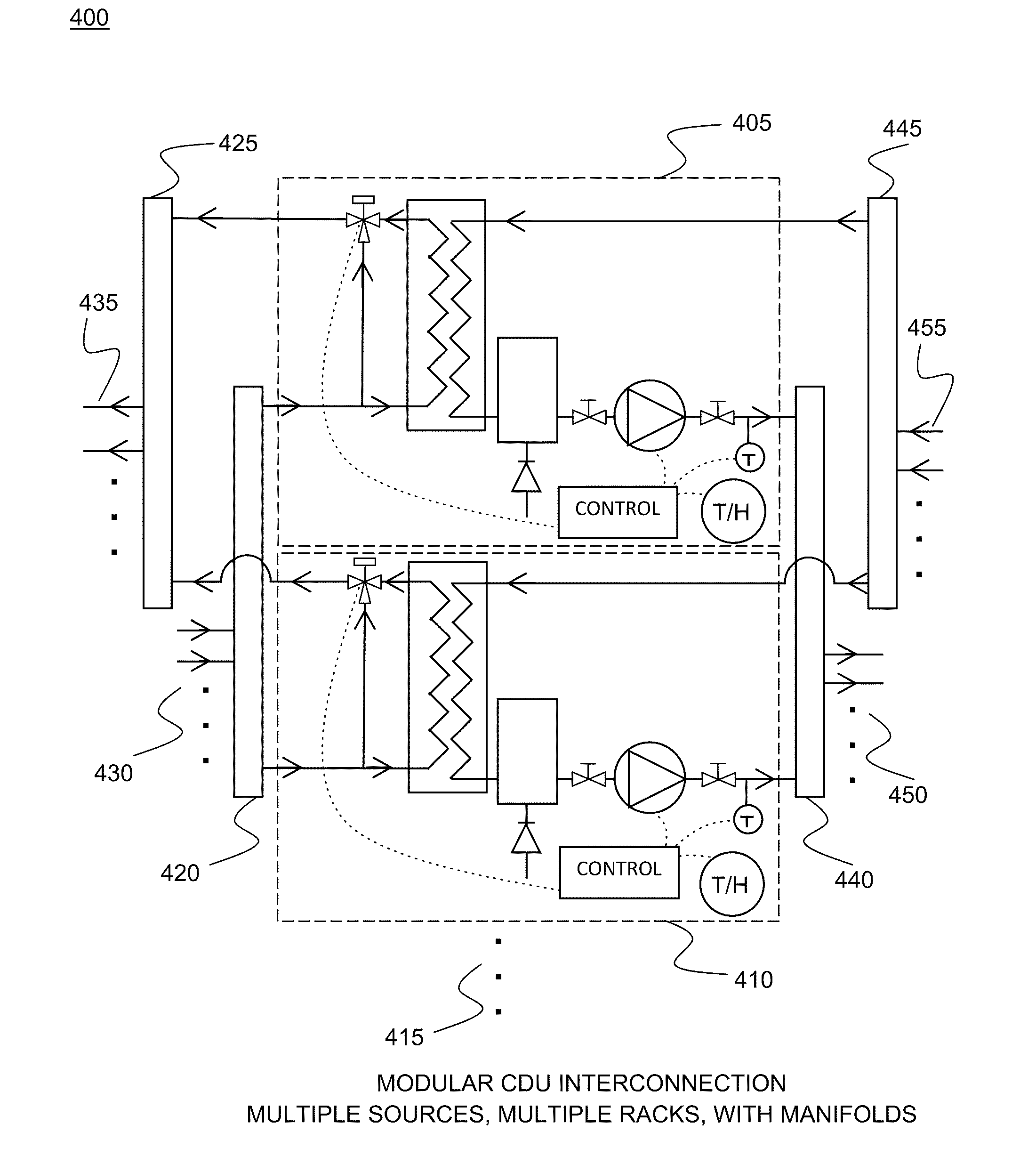
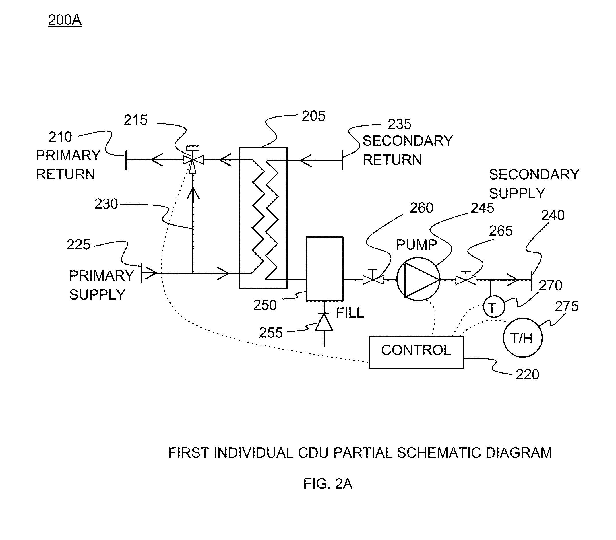
[0057]FIG. 2A illustrates a partial schematic of a scalable modular CDU 200A with heat exchanger 205 including primary return 210 controlled by 3-way valve 215. In embodiments, heat exchanger 205 is a brazed plate heat exchanger. Valve 215 is controlled by control unit 220. Primary supply 225 feeds heat exchanger 205. Valve 215 controls flow between primary supply 225, primary return 210 (through primary coolant loop bypass line 230) and heat exchanger 205. Secondary return 235 is in fluid connection with heat exchanger 205. Secondary supply 240 includes pump 245. Pump 245 is connected to control unit 220. Between pump 245 and heat exchanger 205 is expansion tank 250. Connected to expansion tank 250 is automatic fill system 255. Between expansion tank 250 and pump 245 is first secondary supply valve 260. After pump 245 in secondary supply 240 is second secondary supply valve 265. After valve 265 in secondary supply 240 is coolant temperature sensor 270. Coolant temperature sensor 27...
second embodiment
[0058]FIG. 2B illustrates a partial schematic of a scalable modular CDU 200B with heat exchanger 205 including primary return 210 controlled by control valves 276A & B. In embodiments, control valve control valve 276B is redundant. In embodiments, heat exchanger 205 is a stainless steel brazed plate heat exchanger. Valves 276A & B are controlled by control unit 220. Primary supply 225 feeds heat exchanger 205. Bypass valve 277 controls flow between primary supply 225 and primary return 210. Secondary return 235 is in fluid connection with heat exchanger 205. In embodiments, secondary return 235 comprises internal manifolds or flexible tails, coupling 282 and air eliminator 283. Secondary supply 240 includes pumps 245A & B. In embodiments, pump 245B is redundant. Pumps 245A & B are connected to control unit 220 via speed control 284. Between pumps 245A & B and heat exchanger 205 is auto fill expansion tank 250. Connected to auto fill expansion tank 250 is automatic fill system compri...
embodiment 300
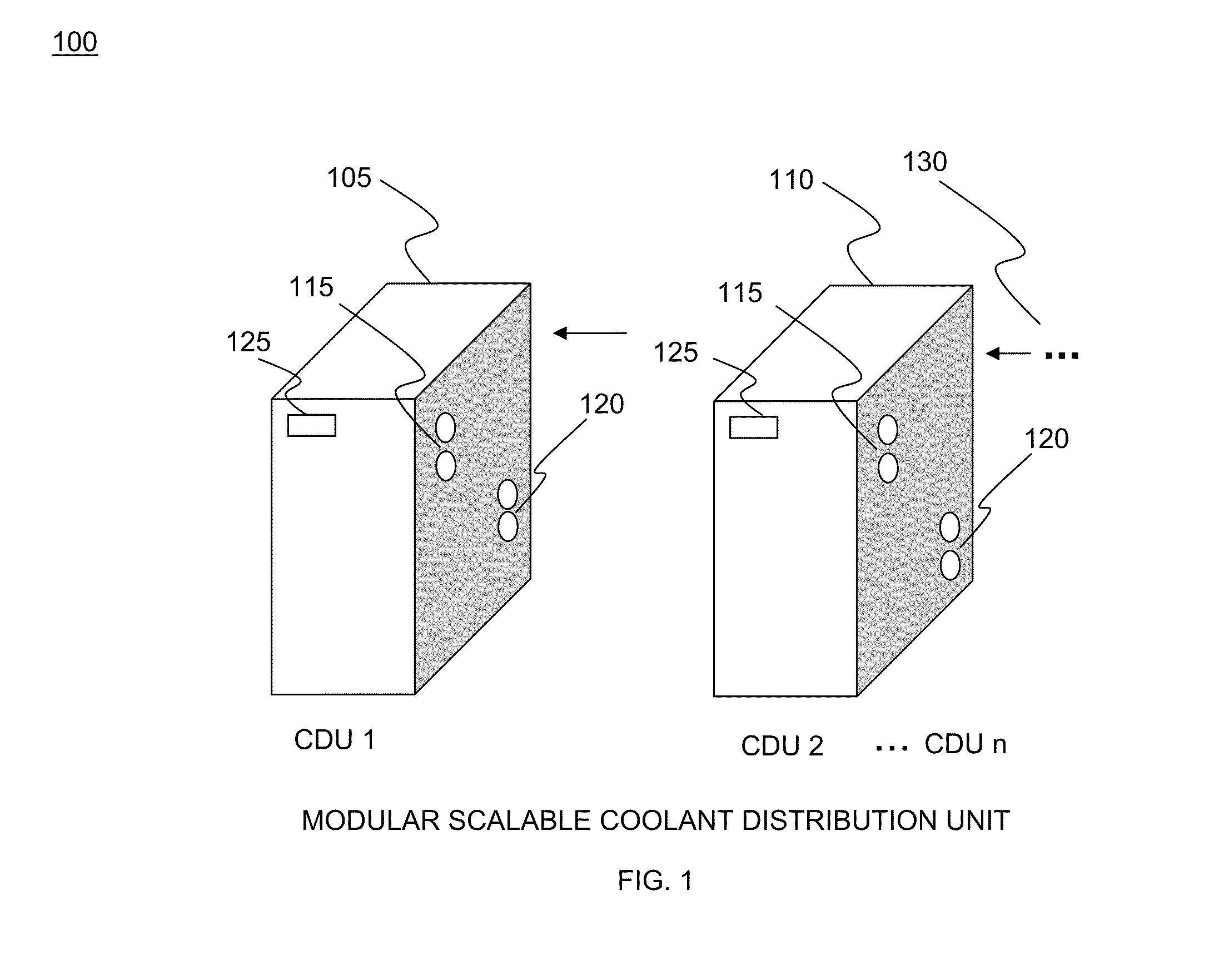
[0059]FIG. 3 is a perspective diagram of a modular scalable CDU cooling system overview embodiment 300 depicting multiple CDUs 305. CDUs 305 are connected by primary loop 310 to cooling source such as facility water 315. CDUs 305 are connected by secondary loop 320 to one or more equipment heat exchangers 325. As non-limiting examples, heat exchangers 325 can be equipment rack rear door liquid to air heat exchangers, room air heat exchangers, direct component liquid cooling heat exchangers, or any combination.
PUM
 Abstract
Description
Claims
Application Information
 - R&D
- Intellectual Property
- Life Sciences
- Materials
- Tech Scout
- Unparalleled Data Quality
- Higher Quality Content
- 60% Fewer Hallucinations
Browse by: Latest US Patents, China's latest patents, Technical Efficacy Thesaurus, Application Domain, Technology Topic, Popular Technical Reports.
© 2025 PatSnap. All rights reserved.Legal|Privacy policy|Modern Slavery Act Transparency Statement|Sitemap|About US| Contact US: help@patsnap.com


