Safety control system for vehicles

a safety control and vehicle technology, applied in the field oftelematics, can solve the problems of increasing the possibility of accidents, using the vehicle telephone by the vehicle driver, and being prone to dangerous situations, so as to reduce the possibility of accidents and reduce or avoid driver distraction

Active Publication Date: 2012-10-30
ACT IP
View PDF152 Cites 119 Cited by
  • Summary
  • Abstract
  • Description
  • Claims
  • Application Information

AI Technical Summary

Benefits of technology

[0006]An object of at least some presently preferred embodiments of the present invention is to provide a safety control system for vehicles tending to reduce the possibility of accidents in one or more of the above respects.

Problems solved by technology

One potentially dangerous condition is the use of a vehicle telephone by the vehicle driver while driving the vehicle.
The use of telematics in general and particularly cellular telephones by drivers while driving has been found to increase the possibility of an accident since such a telephone not only diverts the driver's attention from driving, but also generally requires the use of at least one of the driver's hands and distract the driver's eyes from the road and traffic.
However, such legislation is difficult to enforce and education is not usually effective in assuring driver compliance.
When one hand is occupied by holding a telephone, the danger of causing an accident in an emergency situation is increased because of the additional reaction time required to properly grip the steering wheel with both hands.
Similar danger exists when the driver attempts to control audio and video equipment, e.g. Radio, Music CD, DVD, Books on tape etc., or when the driver attempts to change environmental controls like adjusting the heat or air conditioning, or other vehicle settings.
There are other potentially dangerous conditions and inherent risks in driving that depends on

Method used


Image

  • Safety control system for vehicles
  • Safety control system for vehicles
  • Safety control system for vehicles

Examples


Embodiment Construction

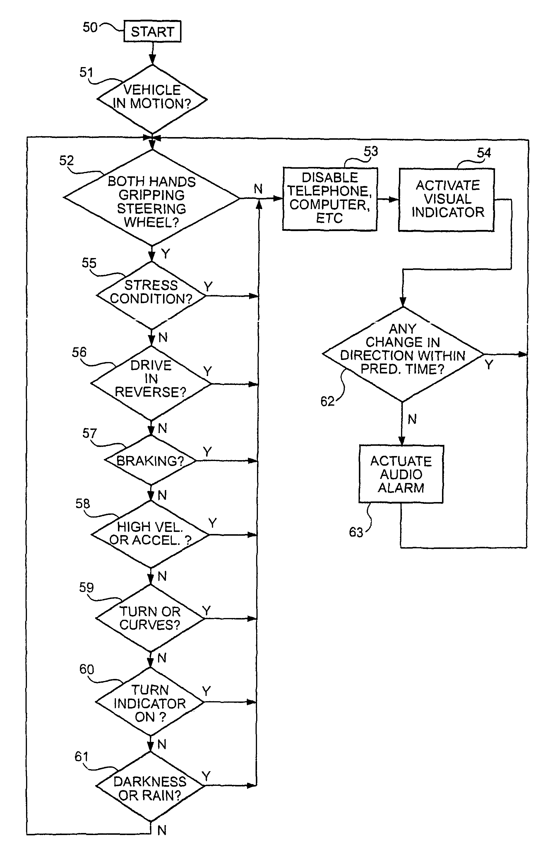
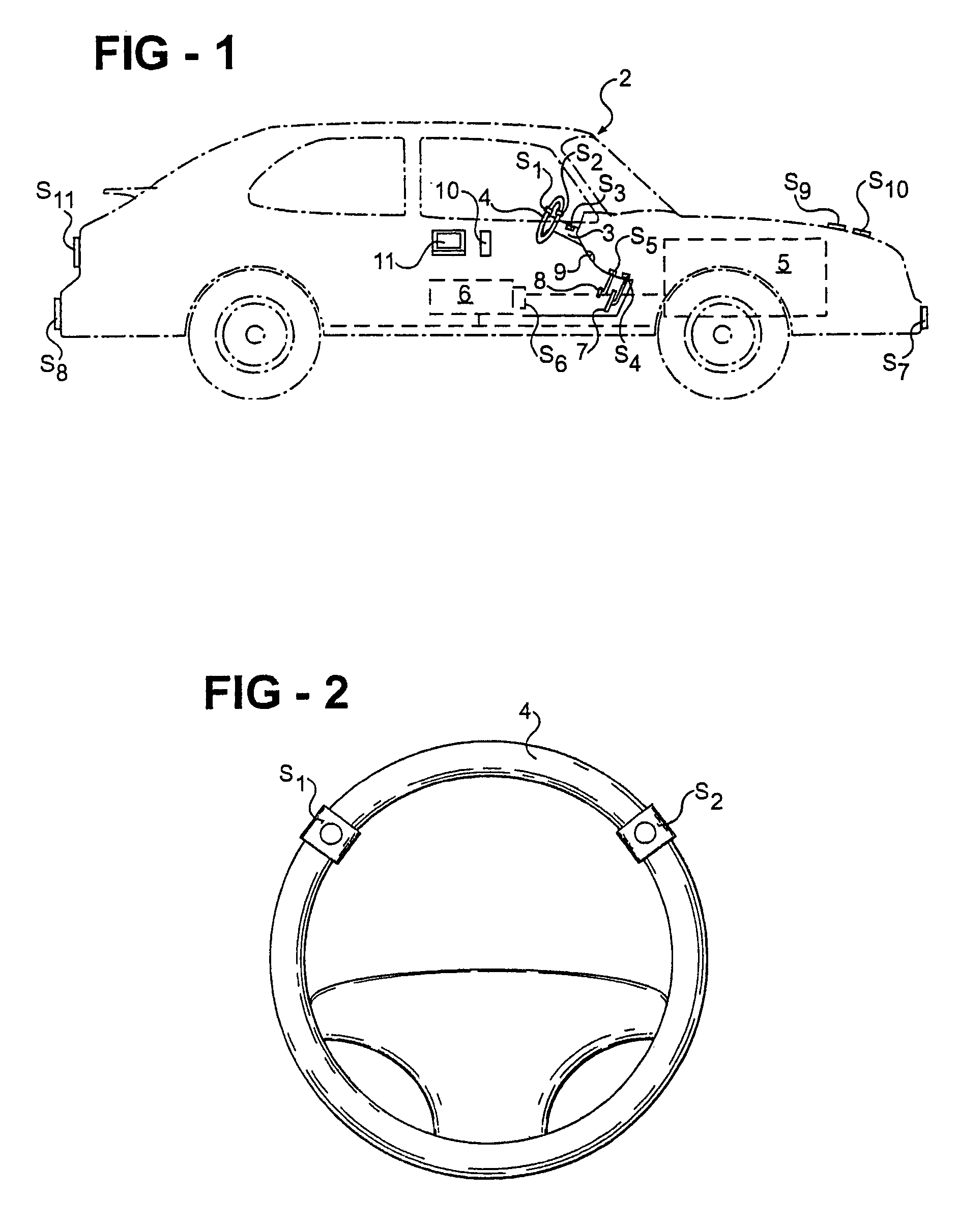
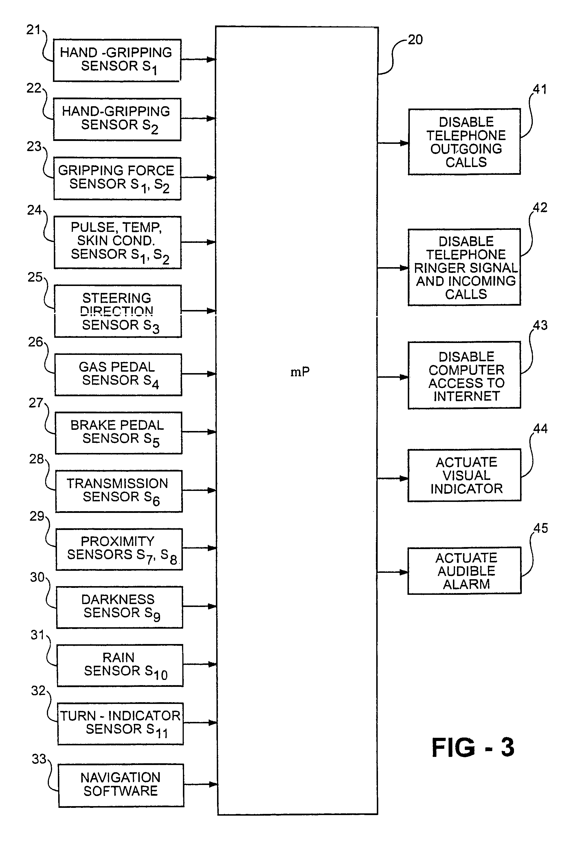
[0033]FIG. 1 schematically illustrates a vehicle, generally designated 2, equipped with a control system for sensing a variety of risk factors and potentially dangerous conditions and for automatically executing various responses when sensing such conditions in order to avoid hazardous situations tending to increase the possibility of an accident. One response is the disabling or suppression of one or more input or output devices to avoid interaction between the devices and the driver in certain situations and conditions. Another response includes providing a signal to or requiring the driver to take some action to increase driver alertness and / or awareness.

[0034]One example of a hazardous situation avoided by the control system illustrated in FIG. 1 is the use of the vehicle telephone in certain situations wherein a making of a telephone call by the vehicle driver, or the receiving of an incoming call, particularly the ringing of such a call, may distract the driver and increase th...


PUM


Abstract

According to one aspect of one embodiment of the present invention, a safety control system for vehicles, includes, a communication device having at least one of an input accessible from within the vehicle and an output communicated within the vehicle, at least one sensor operable to sense at least one condition related to vehicle operation, and a controller communicated with the sensor and the communication device to selectively suppress at least one of said input and said output in response to a sensed parameter of said at least one condition being outside of a threshold. When an input is suppressed, the driver is prevented from accessing or inputting information into the communication device. When an output is suppressed, communication between the device and the driver of a vehicle is suppressed to, among other things, avoid distracting the driver during certain driving situations or conditions relating to the driver, vehicle and/or environment.

Description

REFERENCE TO CO-PENDING APPLICATIONS[0001]The present application is a continuation of U.S. patent application Ser. No. 10 / 287,299, filed Nov. 4, 2002 now U.S. Pat. No. 6,731,925, which claims the benefit of an priority from U.S. patent application Ser. No. 10 / 279,447, filed Oct. 24, 2002, Provisional Application No. 60 / 336,293 filed Oct. 24, 2001, and Provisional Application No. 60 / 390,877 filed Jun. 21, 2002, the contents of which are incorporated herein by reference.FIELD OF THE INVENTION[0002]The present invention relates to the field of telematics, namely to the field of integrating information, communication, computing and entertainment technologies into vehicles for civilian or military use. The invention particularly relates to safety control systems for vehicles to reduce driver distraction, avoiding potentially dangerous conditions tending to produce accidents.BACKGROUND OF THE INVENTION[0003]One potentially dangerous condition is the use of a vehicle telephone by the vehi...

Claims


Application Information

Patent Timeline
IPC IPC(8): H04B1/06B60R11/00B60R11/02G08B21/06H04M1/72463
CPCG06F17/00G08B21/06B60R11/0264B60R2011/001B60K2370/195H04M1/72463H04M1/724631H04M1/6075B60Q9/00B60R16/023G06F3/017G06F3/0227H04M1/6083B60Q9/008B60R16/0232B60W2520/105H04M1/6091
Inventor NABOULSI, MOUHAMAD A.
Owner ACT IP
Why Eureka
Try Eureka