Safety heat exchanger for combining a heat pump with a device of a public drinking water supply facility

a heat exchanger and heat pump technology, applied in the direction of fluid pressure control, heating types, stationary tubular conduit assemblies, etc., can solve the problems of drinking water in reality not completely safe, drinking water is considered a health risk, and the harm of coolant or anti-freeze compound in drinking water can be reliably and safely prevented

Inactive Publication Date: 2012-11-06
VEOLIA EAU COMPAGNIE GENERALE DES EAUX
View PDF16 Cites 1 Cited by
  • Summary
  • Abstract
  • Description
  • Claims
  • Application Information

AI Technical Summary

Benefits of technology

[0012]Finally, the heat pump disclosed in DE 1020040614441 B4 has an intermediate circulation loop which is not primarily designed to protect the drinking water. Instead, the primary circulation loop is filled with drinking water to protect groundwater. The intermediate circulation loop protects the arrangement from freezing and is therefore filled with brine or a water-glycol mixture which is not viewed as being harmless to the drinking water supply. The DE 1020040614441 B4 is hence exclusively directed to a heat exchanger system with a geothermal collector with a drinking water fill, wherein the heat exchanger is typically protected against freezing. The safety heat exchanger is therefore temperature-controlled. A return line is provided which is opened by a thermostat valve when the permissible cooling temperature is attained. In addition, the intermediate circulation loop has a circulation system sized to be adequate for practically preventing freezing.
[0014]The invention is directed to a safety heat exchanger for the combination of a heat pump with a device of a public drinking water supply facility, which has a primary circulation loop with drinking water, a safety circulation loop with a substance that does not pose a health risk, and a tertiary circulation loop with a coolant. The safety heat exchanger should prevent harm to the drinking water in the public drinking water supply. The safety heat exchanger should also prevent a decrease in the quality of the drinking water commensurate with drinking water regulations and protect the health of the population from the harmful contamination. The drinking water must still be fit for consumption and its purity must not be diminished when recovering heat from drinking water intended for human consumption.
[0017]In this way, harm to the drinking water through coolant or anti-freeze compound can be reliably and safely prevented. If a leak occurs between the primary circulation loop or the coolant, overpressure is generated in the intermediate circulation loop, which is monitored with the pressure monitor. In the event of an overpressure or a reduced pressure different from a control pressure, the pumps in all circulation hoops are switched off, and the inlet and outlet of the drinking water to the drinking water supply facility is closed off by magnetic valves, which will be described below with reference to two exemplary embodiments.

Problems solved by technology

However, this alone cannot completely satisfy the requirements for the protection of drinking water, because coolant can be transferred to the drinking water unnoticed if the coolant circulation loop and the intermediate circulation loop develop a leak.
For this reason, the drinking water is in reality not completely safe, because the drinking water circulation loop is in direct contact with the water-glycol intermediate circulation loop.
Glycol in a drinking water supply is considered a substance that poses a health risk.
As a result, the heat exchanger is not suitable for the combination of a heat pump with a device of a public drinking water supply facility.

Method used


Image

  • Safety heat exchanger for combining a heat pump with a device of a public drinking water supply facility
  • Safety heat exchanger for combining a heat pump with a device of a public drinking water supply facility
  • Safety heat exchanger for combining a heat pump with a device of a public drinking water supply facility

Examples


Embodiment Construction

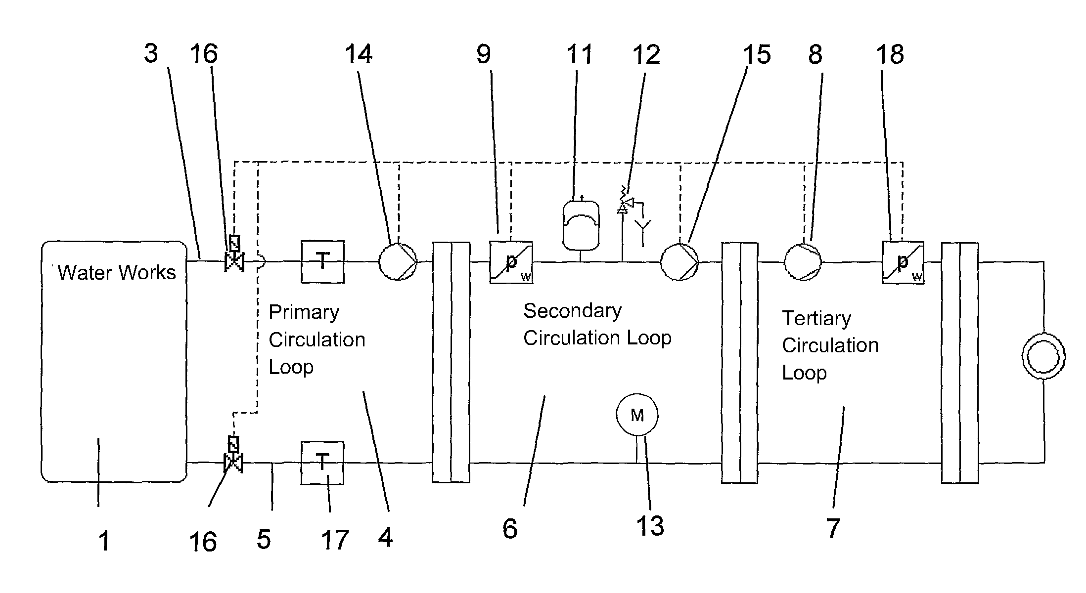
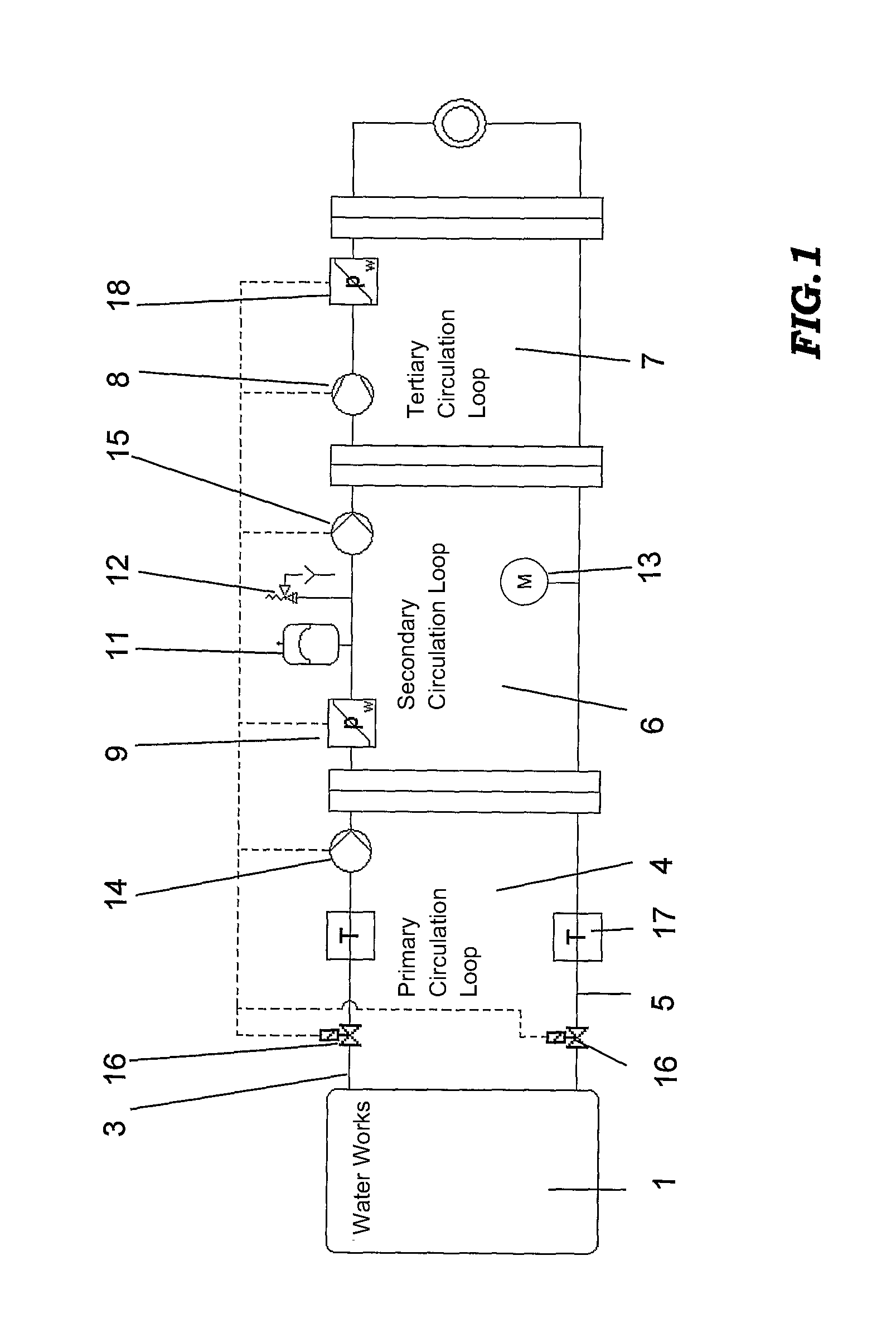
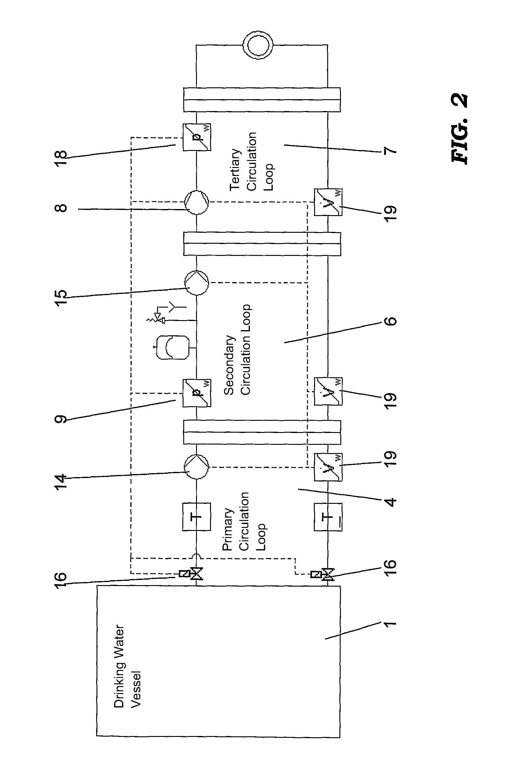
[0021]FIG. 1 shows a safety heat exchanger for the combination of a heat pump with a device of a drinking water supply facility which is represented in the first exemplary embodiment by a waterworks 1. In the second exemplary embodiment illustrated in FIG. 2, the device of the drinking water supply facility is illustrated as a drinking water vessel. The invention should not be considered as limited to facilities of this type. Devices and facilities of drinking water supply facilities may include, for example, facility components for drinking water extraction, pumping stations, pressure boosting stations or drinking water supply networks.

[0022]The device of the drinking water supply facility in FIG. 1 is a waterworks 1, in which primarily for the consumption of the facility and for saving energy, the geothermal energy contained in the drinking water is transferred by a safety heat exchanger in combination with a heat pump to a higher temperature level than the temperature of the drin...


PUM


Abstract

A safety heat exchanger for combining a heat pump with a device of a drinking water supply facility for obtaining heat from drinking water. The heat exchanger includes a primary circulation loop (4) with drinking water, a secondary circulation loop (6) with antifreeze as a material that does not pose a health risk, and a tertiary circulation loop (7) with a coolant. The primary circulation loop (4) includes an inlet (3) connected to a drinking water supply facility and an outlet (5) with electrically controllable magnetic valves (16). The secondary circulation loop (6) and tertiary circulation loop (7) each have any dedicated difference pressure monitor (9, 18), which difference pressure monitors (9, 18) are controllably connected with the magnetic valves (16) such that when the difference pressure monitors (9, 18) detects a pressure difference in the secondary circulation loop (6) and / or in the tertiary circulation loop (7), the inlet (3) and the outlet (5) of the drinking water to the drinking water facility are closed, wherein the difference pressure monitor (9) of the secondary circulation loop (6) comprises an expansion vessel (11), a safety valve (12) and a manometer (13).

Description

[0001]This application is a 371 application of PCT / DE2008 / 001403 filed Aug. 26, 2008, which claims priority to the German application DE 10 2007 040 629.2 filed Aug. 27, 2007.BACKGROUND OF THE INVENTION[0002]The invention relates to safety heat exchanger for a combination of a heat pump with a device of a drinking water supply facility, with a primary circulation loop with drinking water, a secondary safety circulation loop with an anti-freeze material that does not pose a health risk, and a tertiary circulation loop with a coolant.[0003]DE 102004061441 B4 discloses a heat exchanger for use in a drinking water sanctuary. For safety reasons, a third intermediate circulation loop is proposed in order to be able to operate the primary circulation with drinking water, with the intent to protect the drinking water in drinking water sanctuaries.[0004]DE 2834442 A1 already disclosed a combination of a drinking water supply facility with a heat exchanger for obtaining heat. For obtaining do...

Claims


Application Information

Patent Timeline
Patent Type & Authority Patents(United States)
IPC IPC(8): F28D7/10
CPCF24D17/02
Inventor BULL, DETLEF
Owner VEOLIA EAU COMPAGNIE GENERALE DES EAUX
Why Eureka
Try Eureka