
Ball array mask and ball array mask supporting apparatus

a technology of supporting apparatus and ball array mask, which is applied in the direction of non-electric welding apparatus, manufacturing tools, and soldering apparatus, etc., can solve the problems of metal mask crimping, metal mask corners being pulled, and insufficient tensile force being imparted to the center portions of respective sides of metal mask, so as to enhance the degree of plane accuracy of the ball array mask

Inactive Publication Date: 2012-11-06
SHIBUYA IND CO LTD
View PDF2 Cites 1 Cited by
  • Summary
  • Abstract
  • Description
  • Claims
  • Application Information

AI Technical Summary

Benefits of technology

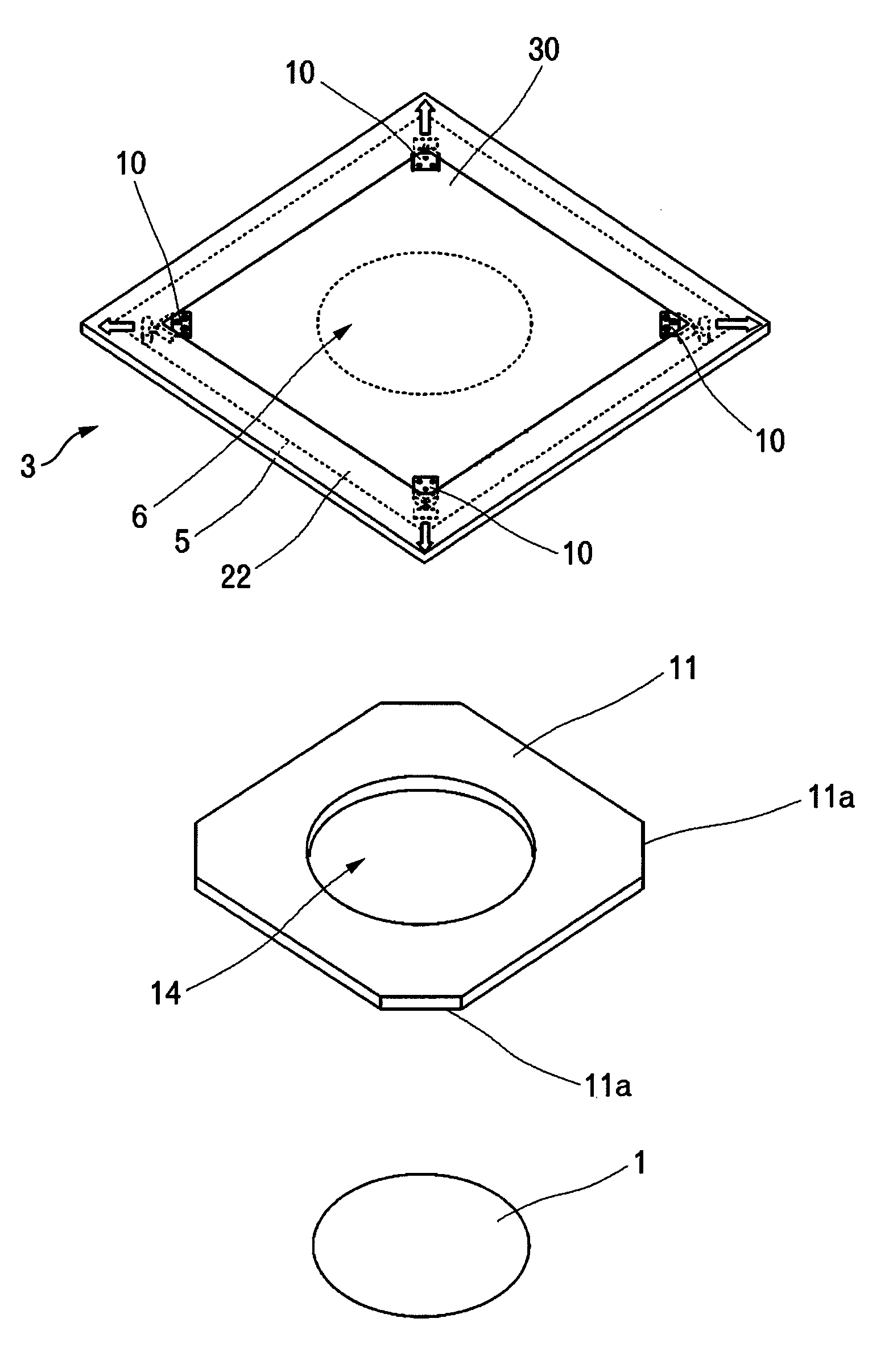
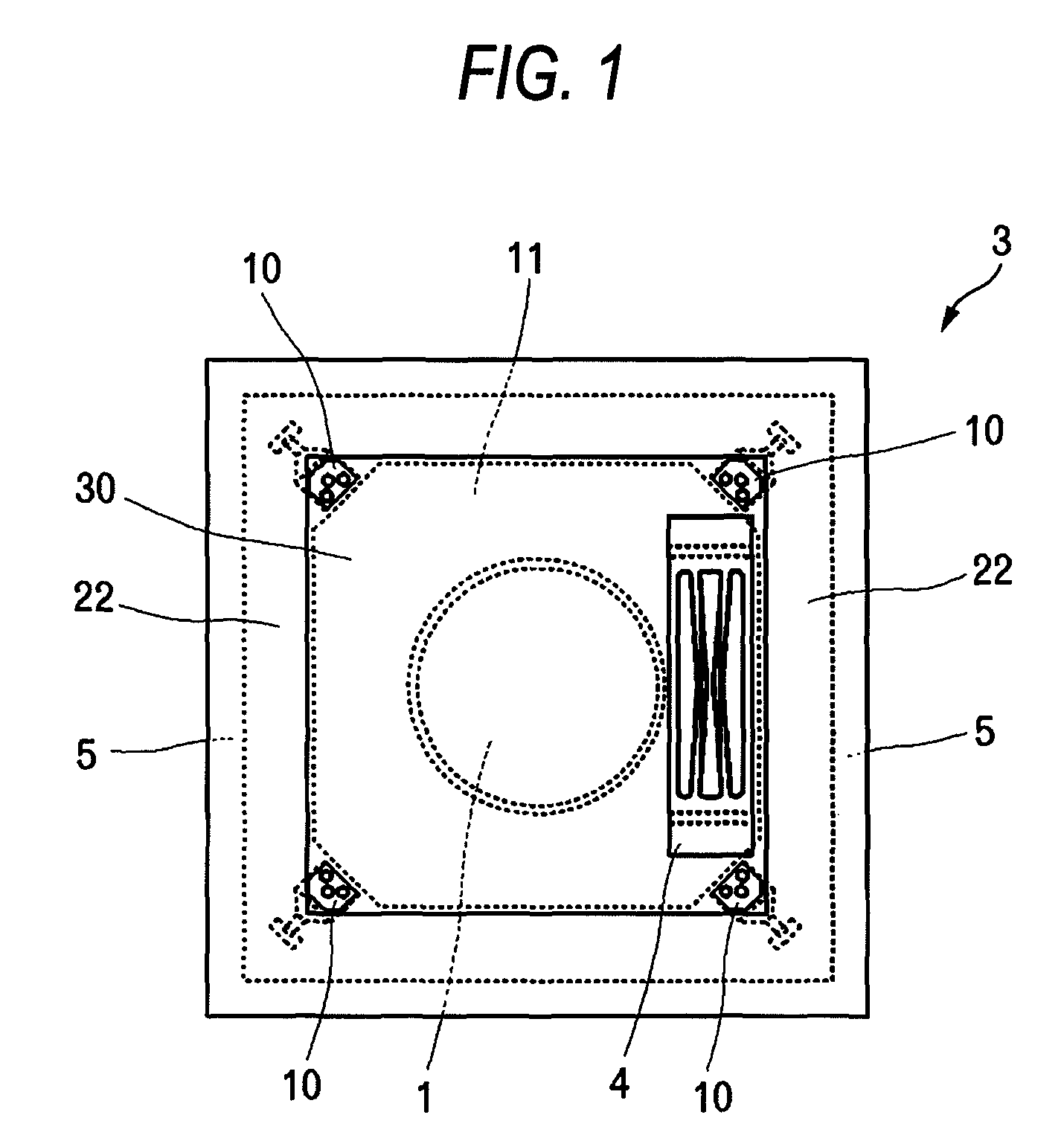
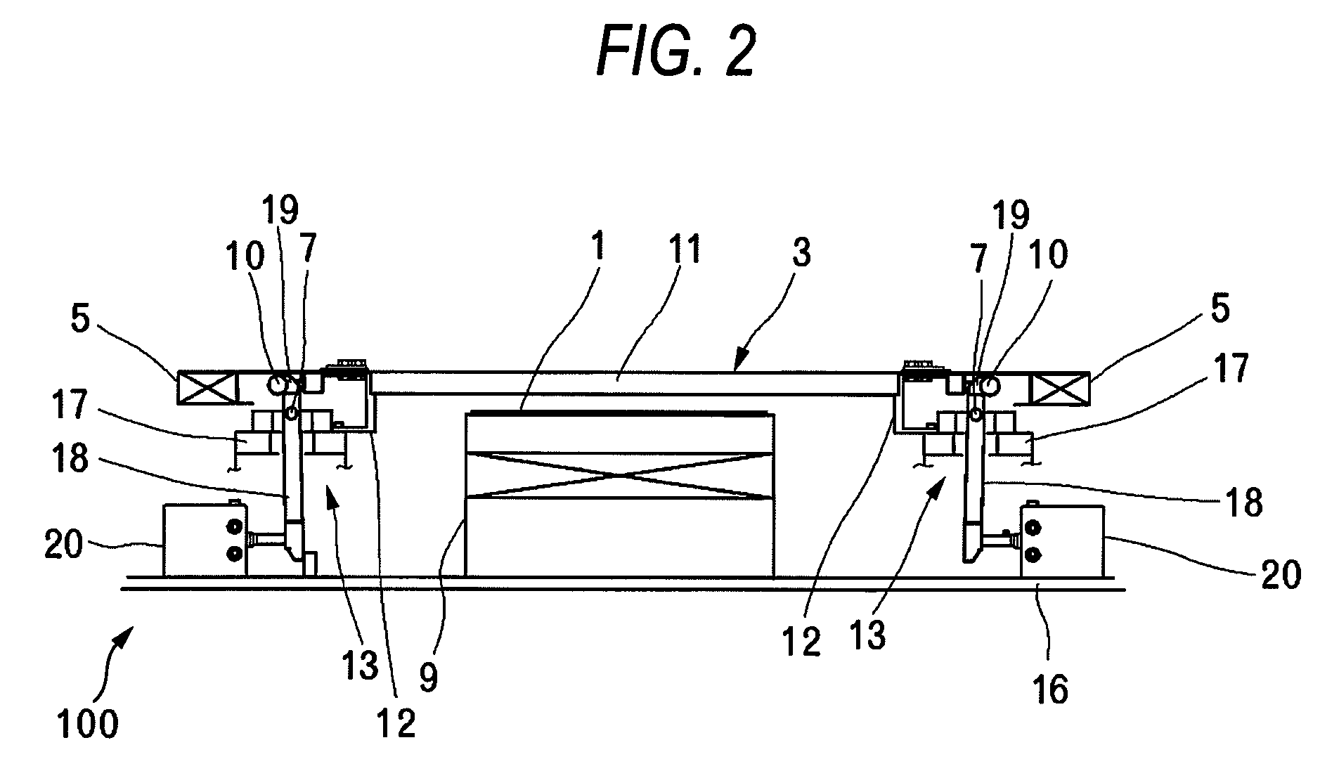
The present invention aims to enhance the accuracy of a metal mask used in a ball array mask. The invention involves affixing the edges of the metal mask to a hollow frame using a stretchable sheet, and providing projection members at the corners of the mask to pull it outwardly. This results in a uniform tensile force applied to the mask, which improves its accuracy when positioned above an object to be mounted. Additionally, a ball array mask supporting apparatus is also provided that includes tensile force imparting units that pull the mask against a contact member surrounding the object to be mounted, further improving the accuracy of the mask.

Problems solved by technology

However, the tensile force imparting unit pulls the corners of the metal mask.
However, there has also arisen a case where insufficient tensile force is imparted to center portions of respective sides of the metal mask.
Since the metal mask is made of metal, such as very thin nickel, there is a risk of the metal mask being crimped in some way of holding at the time of operation for attaching and detaching the metal mask to and from the ball array mask supporting apparatus or a potential risk of a finger being cut by a sharp edge of the metal mask.
Thus, the metal mask is difficult to handle.

Method used


Image

  • Ball array mask and ball array mask supporting apparatus
  • Ball array mask and ball array mask supporting apparatus
  • Ball array mask and ball array mask supporting apparatus

Examples


Embodiment Construction

[0018]A working mode of the present invention is hereunder described along with an embodiment and by reference to the drawings. The embodiment relates to a solder ball mounting apparatus. The solder ball mounting apparatus has a wafer carrying-in delivery part, a flux print part, a ball mounting part, and a wafer carrying-out part. A ball array mask and an apparatus supporting the ball array mask pertaining to the present invention are used in the ball mounting part.

[0019]Minute balls of the present invention include solder balls, platinum balls, and the like, which correspond to conductive balls. An object on which the minute balls are to be mounted includes a semiconductor wafer (hereinafter described simply as a “wafer”), an electronic circuit board, a ceramic board, and others. Solder balls and a wafer are used in the embodiment. Flux, a solder paste, a conductive adhesive, and the like, is used as an adhesive material. In the embodiment, flux is used, and electrodes on the wafe...


PUM

PropertyMeasurementUnit
thicknessaaaaaaaaaa
shapeaaaaaaaaaa
tensile forceaaaaaaaaaa

Abstract

A ball array mask includes: a metal mask, which includes through holes into which minute balls are inserted, and which is positioned at a location above an object to be mounted; a hollow frame; a stretchable sheet, edges of the metal mask being affixed to the hollow frame by the stretchable sheet; and projection members that are attached to respective corners of the metal mask so as to pull the metal mask outwardly.

Description

[0001]This application claims priority from Japanese Patent Application No. 2008-212970 filed on Aug. 21, 2008, the entire subject matter of which is incorporated herein by reference.BACKGROUND OF THE INVENTION[0002]1. Field of the Invention[0003]The present invention relates to a ball array mask and a ball array mask supporting apparatus. The present invention has been developed with mainly focus on a ball array mask and a ball array mask supporting apparatus utilized for a system that arrays minute balls by relatively moving a ball cup storing the minute balls over an array mask having through holes by way of which the balls are inserted into a predetermined pattern.[0004]2. Description of the Related Art[0005]In a solder ball mounting apparatus that mounts solder balls on respective electrodes formed on a wafer, which is an object to be mounted, in a predetermined array pattern, the number of solder balls to be mounted by one operation is increased as a result of miniaturization ...

Claims


Application Information

Patent Timeline
Patent Type & Authority Patents(United States)
IPC IPC(8): B23K1/00
CPCB23K3/0623
Inventor KAJII, YOSHIHISA
Owner SHIBUYA IND CO LTD
Learn More