Blade pitch driving apparatus for wind driven generator

a technology of driving apparatus and turbine, which is applied in the direction of rotors, marine propulsion, vessel construction, etc., can solve the problems of increasing maintenance challenges, increasing system costs, and failure of pitch drive, so as to reduce fabrication costs, simplify structure, and reduce maintenance costs.

Active Publication Date: 2012-11-06
IND TECH RES INST
View PDF21 Cites 2 Cited by
  • Summary
  • Abstract
  • Description
  • Claims
  • Application Information

AI Technical Summary

Benefits of technology

[0020]In consequence, the present invention utilizes an ACPM instead of a DC motor, no carbon brush or commutator is required. Additionally, the ACPM is selectively connected with the external electrical power (driving electrical power from PMSM drive) or the uninterruptible electrical power. Accordingly, the present invention has satisfactory redundancy design, simplified structure and lower fabrication cost.

Problems solved by technology

These factors contribute to an increased challenge in maintenance and a higher cost of the system.
Thus, the failure of the pitch drive cannot be completely avoided and it is usually required that the pitch drive should have a redundancy design for consideration of the system reliability.
Further, no ventilating or cooling system is disposed in the wind generator hub.
Under heavy load conditions, accordingly the winding is easily overheated and the pitch motor might be therefore burnt out.
In view of the above-mentioned disadvantages of the DC motor applied to a large scale wind-driven generator, the operation maintenance requirement and cost are relatively high.
Although the above-mentioned published European patent EP1664527 adopts an AC motor, the similar redundancy design still has large complication or higher fabrication cost, and requires more backup batteries.

Method used


Image

  • Blade pitch driving apparatus for wind driven generator
  • Blade pitch driving apparatus for wind driven generator
  • Blade pitch driving apparatus for wind driven generator

Examples


Embodiment Construction

[0030]The embodiments given below in the invention are only used to illustrate the objectives and the preferred embodiments of the invention, and are not used to limit the scope of the invention.

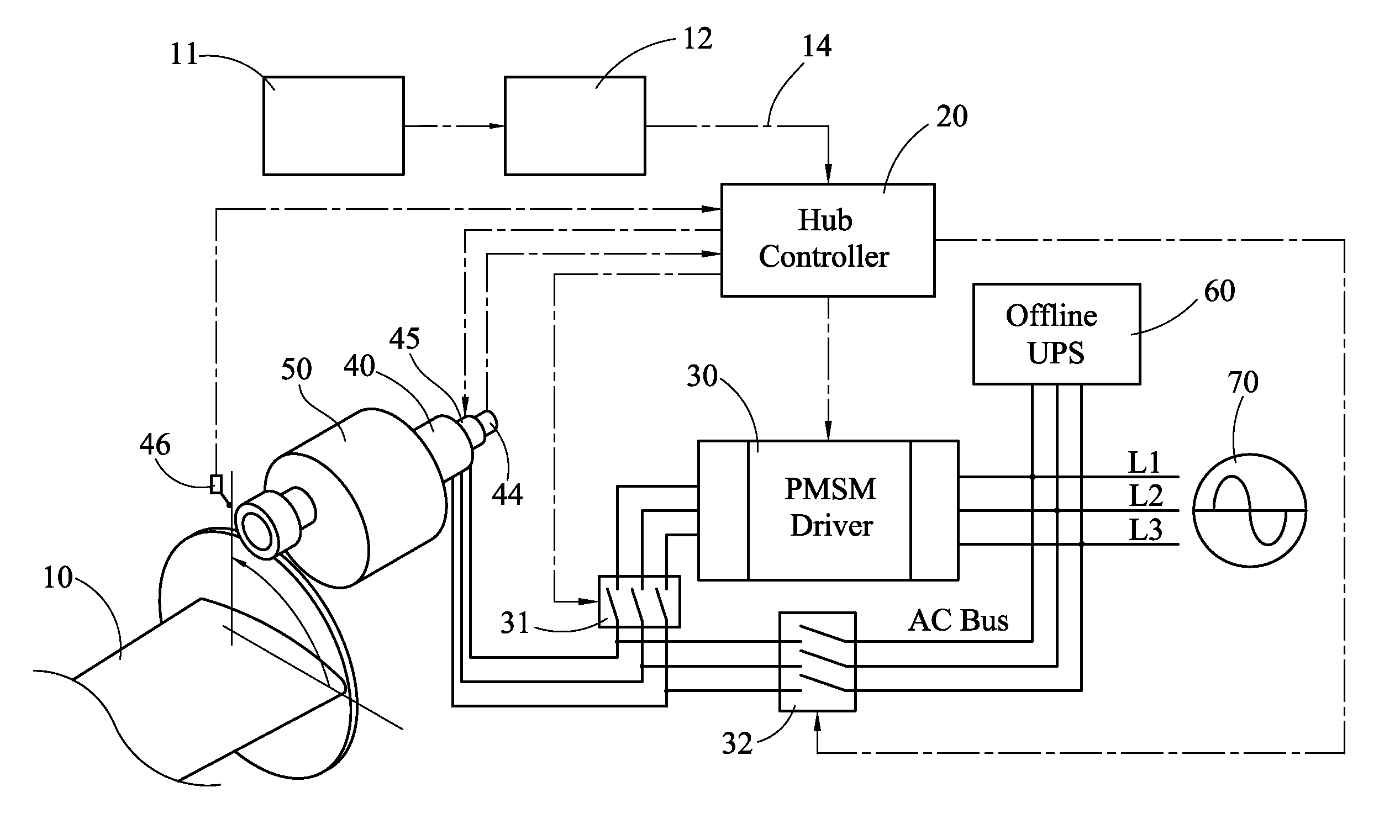
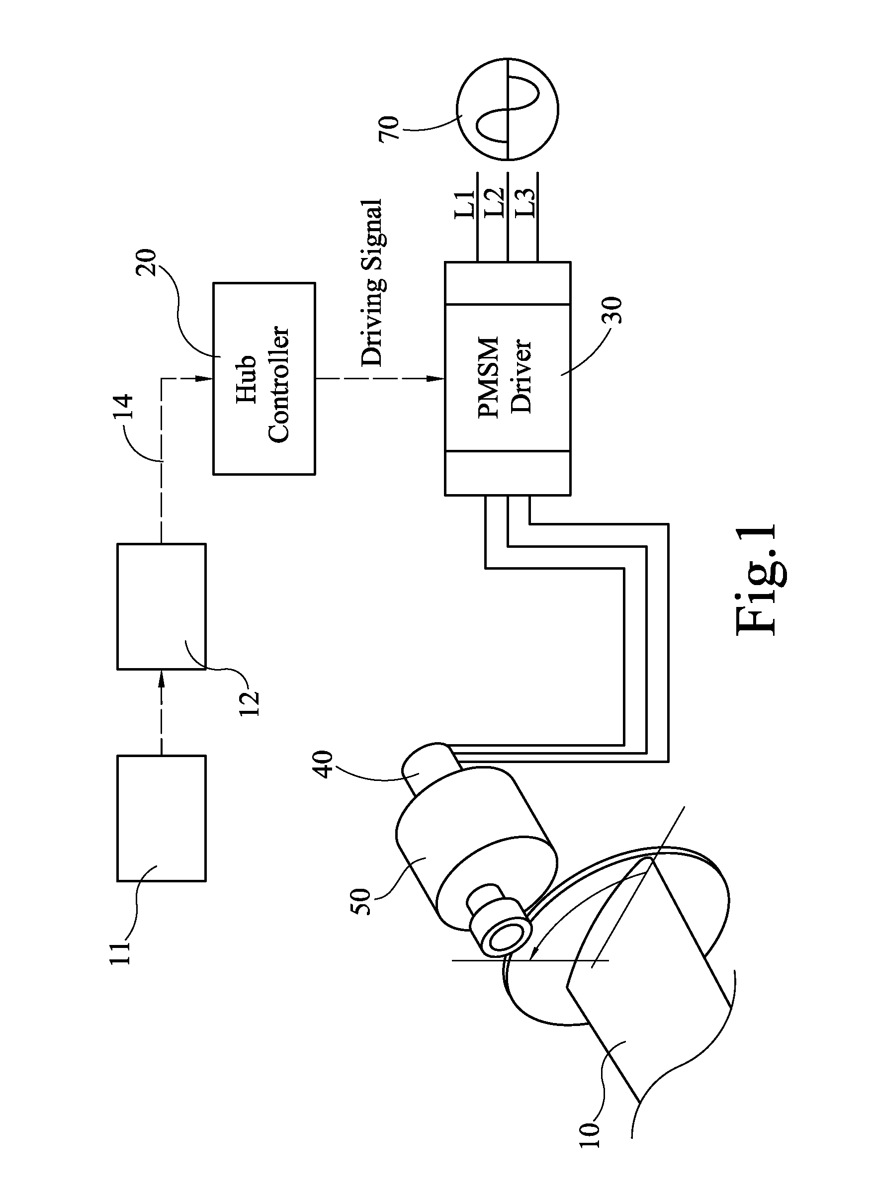
[0031]In general, a wind-driven generator usually has three blades (or less than or more than three blades), and a blade pitch driving apparatus is installed in a hub of the wind-driven generator, for driving a corresponding blade 10 to rotate to a predetermined blade pitch. An anemometer 11 and a central control part 12 (see FIG. 1) are provided in a nacelle of the wind-driven generator. The central control part 12 determines the pitch of the blade according to a current wind speed, and sends a pitch command 14 to the blade pitch driving apparatus, for driving the blade 10 to rotate to a corresponding pitch position in accordance with the pitch command 14.

[0032]According to one embodiment of the invention, a suit of corresponding blade pitch driving apparatus is provided for each blade 10 o...


PUM


Abstract

A blade pitch driving apparatus of a wind-driven generator and a driving method therefor are adapted to receive an external electrical power and impel a blade toward a corresponding pitch angle according to a pitch command. The apparatus includes an UPS, a permanent magnet synchronous motor drive (PMSM drive), an AC pitch motor (ACPM) and a hub controller. The hub controller normally switches the external power to the PMSM drive, receives the pitch command and control the ACPM to impel the blade toward the corresponding pitch angle. When the PMSM drive fails or the external electrical power is interrupted, the hub controller switches the electrical power of the UPS to the ACPM and controls the blade being impelled toward a feathered position.

Description

CROSS-REFERENCE TO RELATED APPLICATIONS[0001]This non-provisional application claims priority under 35 U.S.C. §119(a) on Patent Application No(s). 096148070 and 097140081 respectively filed in Taiwan, R.O.C. on Dec. 14, 2007 and Oct. 17, 2008 the entire contents of which are hereby incorporated by reference.BACKGROUND OF THE INVENTION[0002]1. Field of Invention[0003]The invention relates to a driving apparatus for a wind-driven generator. More particularly, the invention relates to a pitch driving apparatus used to adjust the pitch angle of the blade of a wind-driven generator.[0004]2. Related Art[0005]During the recent years, the output power of a wind driven generator has been increased to more than 5000 kW, and the length of the blade and tower height are extended over tens of meters. These factors contribute to an increased challenge in maintenance and a higher cost of the system. On the other hand, to reduce the cost of power generation and ensure the operational profit, the se...

Claims


Application Information

Patent Timeline
Patent Type & Authority Patents(United States)
IPC IPC(8): F03D7/00F01D7/00
CPCF03D7/0224F05B2260/77F05B2260/79F05B2270/328Y02E10/723Y02E10/72
Inventor GUEY, ZEN-JEYTUNG, CHIEN-CHIANGCHANG, YUN-YUAN
Owner IND TECH RES INST
Why Eureka
Try Eureka