Heat dissipation structure of electronic device

a technology of electronic devices and heat dissipation structures, which is applied in the direction of electrical apparatus casings/cabinets/drawers, semiconductor/solid-state device details, instruments, etc., can solve the problems of affecting the heat dissipation efficiency affecting the temperature of airflow, and relatively causing heat dissipation problems of other electronic elements, etc., to achieve the effect of desired heat dissipation efficiency

Active Publication Date: 2012-11-06
IND TECH RES INST
View PDF25 Cites 41 Cited by
  • Summary
  • Abstract
  • Description
  • Claims
  • Application Information

AI Technical Summary

Benefits of technology

[0014]According to the heat dissipation structure of the electronic device according to the present disclosure, the condensation end of the heat pipe is directly inserted in the chamber of the cooler. The condensation end directly exchanges heat with the cooling fluid, so as to achieve desired heat dissipation efficiency. Moreover, even though there is mating tolerance between the heat pipe and the cooler, it can be ensured that the condensation end is kept to be immersed in the cooling fluid, as long as the condensation end is positioned in the chamber. Therefore, the problem existing in the prior art of unobvious heat dissipation effect caused by the poor contact of the heat pipe with the cooler can be effectively solved by the heat dissipation structure of the electronic device according to the present disclosure.

Problems solved by technology

However, the heat dissipation problem of other electronic elements is relatively caused while the heat sink dissipates the heat of CPU.
For example, when airflow flows through the CPU and removes the heat energy generated by the CPU, the temperature of the airflow is raised, and such high-temperature airflow is adverse to the heat dissipation of other electronic elements.
However, the system load is caused to be relatively increased if the power of the air supply device for heat dissipation is improved.
Moreover, the smaller volume of the server results in the smaller inner spacing for circulating of the airflow, and thus the heat dissipation effect using heat convection becomes much poorer.
Therefore, the space in the server will be filled with more electronic elements and becomes congested, and thus excessive accumulation of the heat energy is caused.
Therefore, when the condensation end is mated with the cooler, if a gap therebetween is too large, the heat dissipation effect is easily caused to be poor due to the incomplete contact between the condensation end and the cooler.
Alternatively, if the mating gap between the condensation end and the cooler is too small, interference and collision with each other easily occur, thereby causing the damage.

Method used


Image

  • Heat dissipation structure of electronic device
  • Heat dissipation structure of electronic device
  • Heat dissipation structure of electronic device

Examples


Embodiment Construction

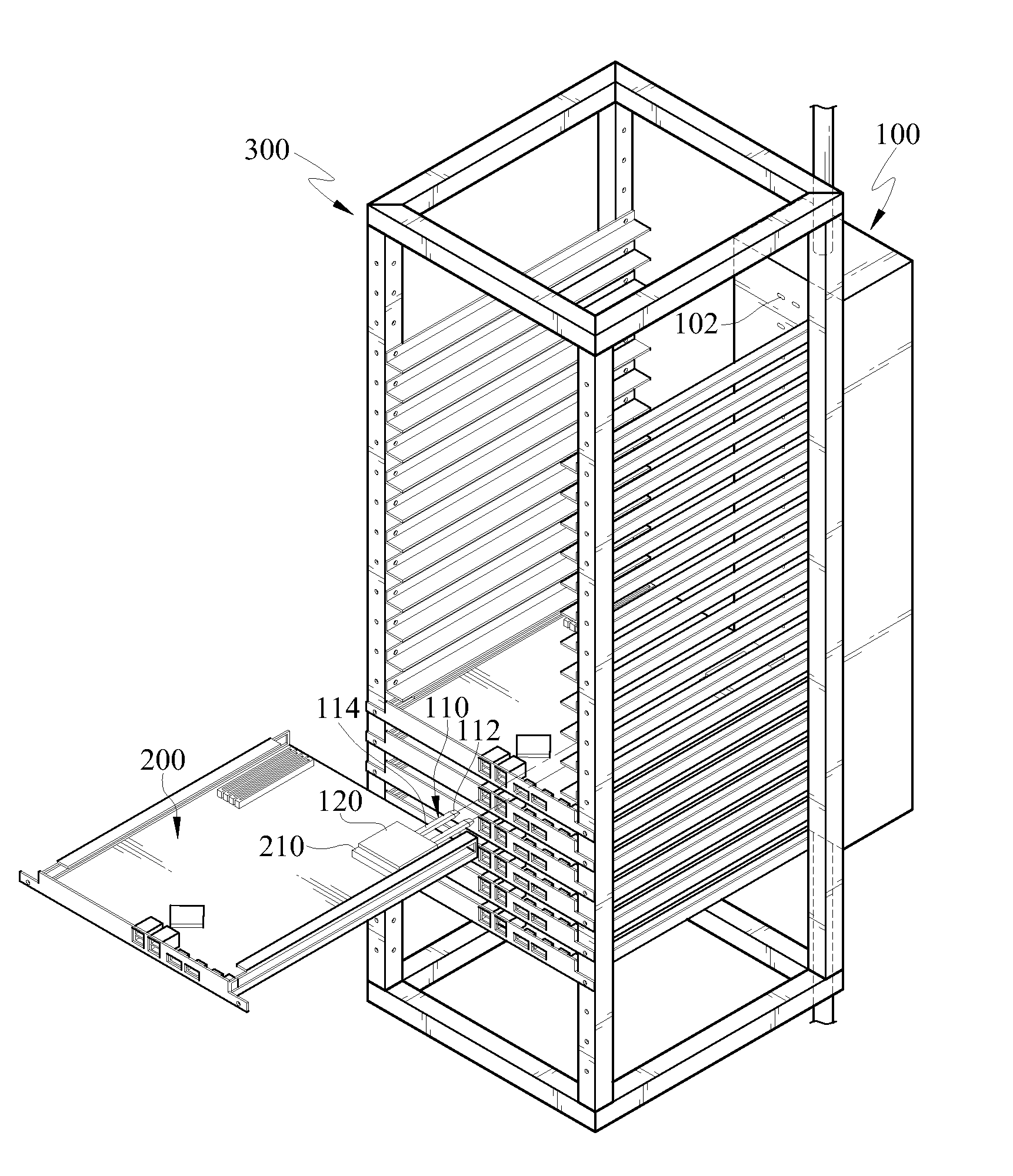
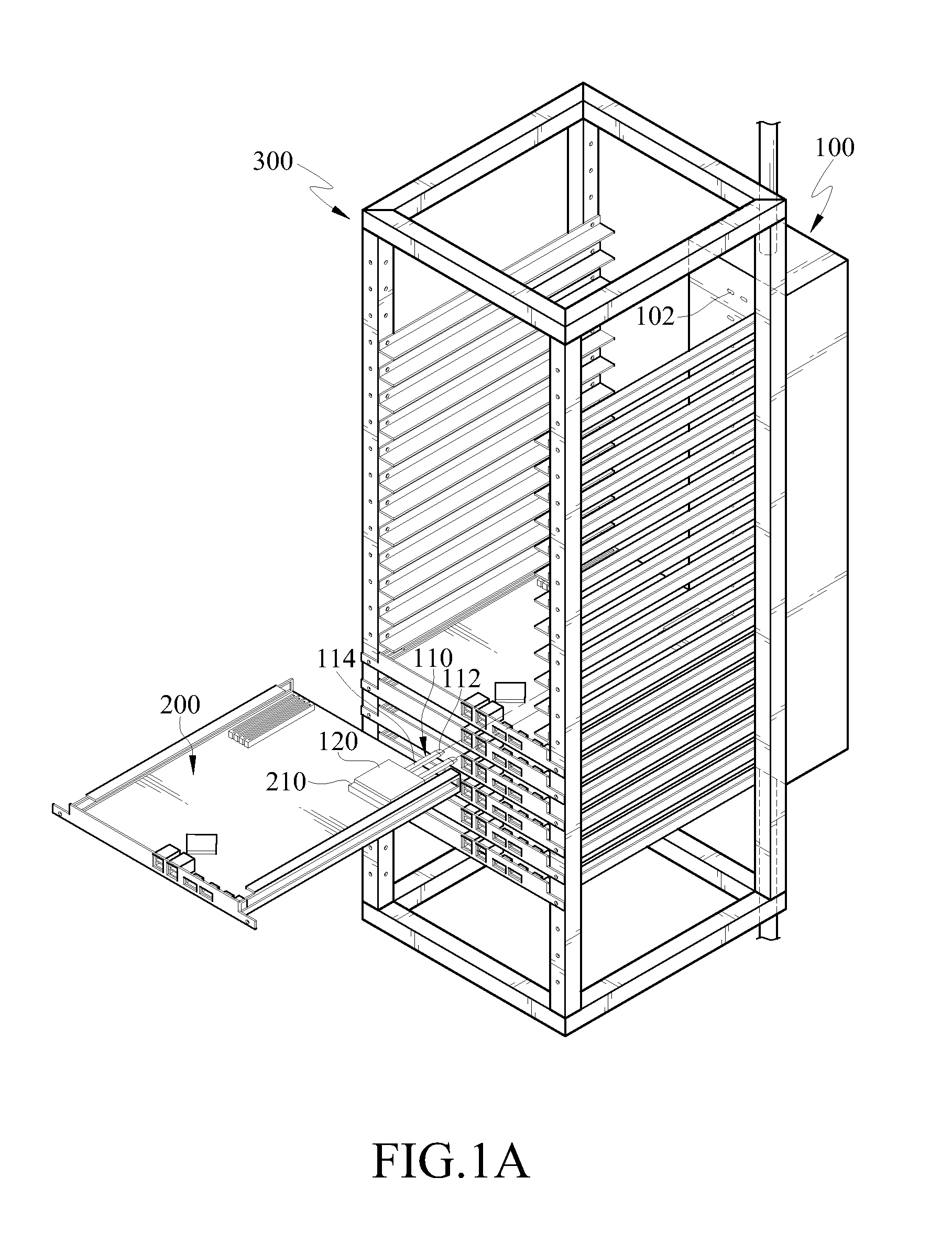
[0032]FIG. 1A is a schematic structural view of a heat dissipation structure of an electronic device according to an embodiment of the present disclosure, and FIG. 2A is a cross-sectional view of a heat pipe and a cooler according to an embodiment of the present disclosure.

[0033]The heat dissipation structure of the electronic device according to the embodiment of the present disclosure is used to dissipate the heat energy of a heat generating element 210 of at least one electronic device 200. In addition, the electronic device 200 is removably disposed in a rack 300.

[0034]In this embodiment, the electronic device 200 and the heat generating element 210 are described with a server and a CPU on a main board of the server as examples, and the rack 300 is described with a server cabinet for mounting the server as example; however, the above examples are not intended to limit the present disclosure. As shown in FIG. 1A, the rack 300 (server cabinet) is mounted with a plurality of electr...


PUM


Abstract

A structure of heat dissipation of an electronic device includes at least one heat pipe and a cooler. The heat pipe has a condensation end and an evaporation end opposite to each other, and the evaporation end is disposed on a heat generating element of the electronic device. The cooler is disposed on a rack and has a chamber therein, and the chamber has an inner shell having a cooling fluid therein. When the electronic device is mounted in the rack, the condensation end of the heat pipe is inserted into the cooler and positioned into the inner shell. The evaporation end absorbs the heat energy of the heat generating element, and transfers the heat energy to the condensation end, such that the cooling fluid dissipates the heat energy of the condensation end.

Description

CROSS-REFERENCE TO RELATED APPLICATIONS[0001]This non-provisional application claims priority under 35 U.S.C. §119(a) on Patent Application No(s). 099137343 filed in Taiwan, R.O.C. on Oct. 29, 2010, the entire contents of which are hereby incorporated by reference.BACKGROUND[0002]1. Field[0003]The present disclosure relates to a heat dissipation structure of an electronic device, and more particularly to a heat dissipation structure of a server device for heat dissipation using a cooling fluid.[0004]2. Related Art[0005]At present, a heat dissipation module used for a central processing unit (CPU) of a server generally employs a heat sink structure. The principle is using a large contact area between the heat sink and the air, and using heat convection to help the heat dissipation of the CPU. However, the heat dissipation problem of other electronic elements is relatively caused while the heat sink dissipates the heat of CPU.[0006]For example, when airflow flows through the CPU and r...

Claims


Application Information

Patent Timeline
Patent Type & Authority Patents(United States)
IPC IPC(8): H05K7/20G06F1/20H01L23/427
CPCH05K7/20781H05K7/20809F28D15/0275F28F2225/04
Inventor WU, HSI-SHENGCHIANG, HSU-CHENGHUNG, KUO-SHULIN, NENG-TAN
Owner IND TECH RES INST
Why Eureka
Try Eureka