
Vehicle travel support device, vehicle, and vehicle travel support program

a technology for vehicle travel and support devices, which is applied in the direction of underwater vessels, driver input parameters, and non-deflectable wheel steering. it can solve the problem of relatively weak vehicle travel suppor

Active Publication Date: 2012-11-06
HONDA MOTOR CO LTD
View PDF27 Cites 4 Cited by
  • Summary
  • Abstract
  • Description
  • Claims
  • Application Information

AI Technical Summary

Benefits of technology

The present invention provides a vehicle travel support device that can operate continuously even when the recognition accuracy of the lane mark is degraded. The device uses a first processing element to recognize the lane mark and a second processing element to control the operation of either the steering device or the braking device. The higher the reliability of the lane mark, the higher the degree of control on the operation of either the steering device or the braking device. This allows for appropriate control to prevent the vehicle from leaving the travel area. The device can adjust the gain coefficient and the number of controlled variables based on the reliability of the lane mark and the reliability of the travel area demarcated by the lane mark, ensuring effective support for the vehicle's travel. The invention also includes a vehicle travel support program and a vehicle travel support device that functions to control the steering and braking devices of the vehicle.

Problems solved by technology

Even when the reliability of the lane mark and the reliability of the travel area are low, the travel of the vehicle is supported relatively weakly without interruption.

Method used


Image

  • Vehicle travel support device, vehicle, and vehicle travel support program
  • Vehicle travel support device, vehicle, and vehicle travel support program
  • Vehicle travel support device, vehicle, and vehicle travel support program

Examples


Embodiment Construction

[0025]An embodiment of a vehicle travel support device and the like according to the present invention will be described with reference to the drawings.

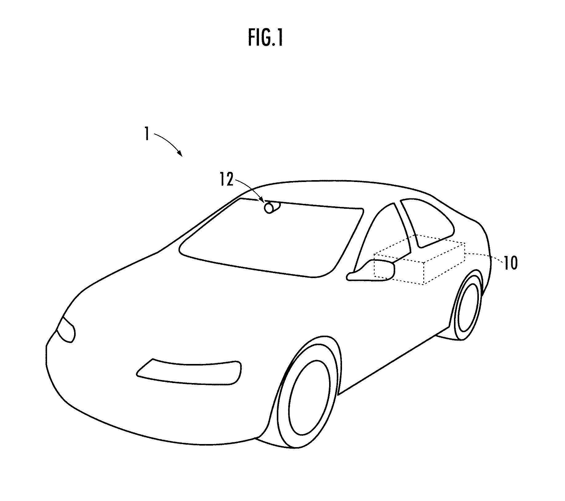
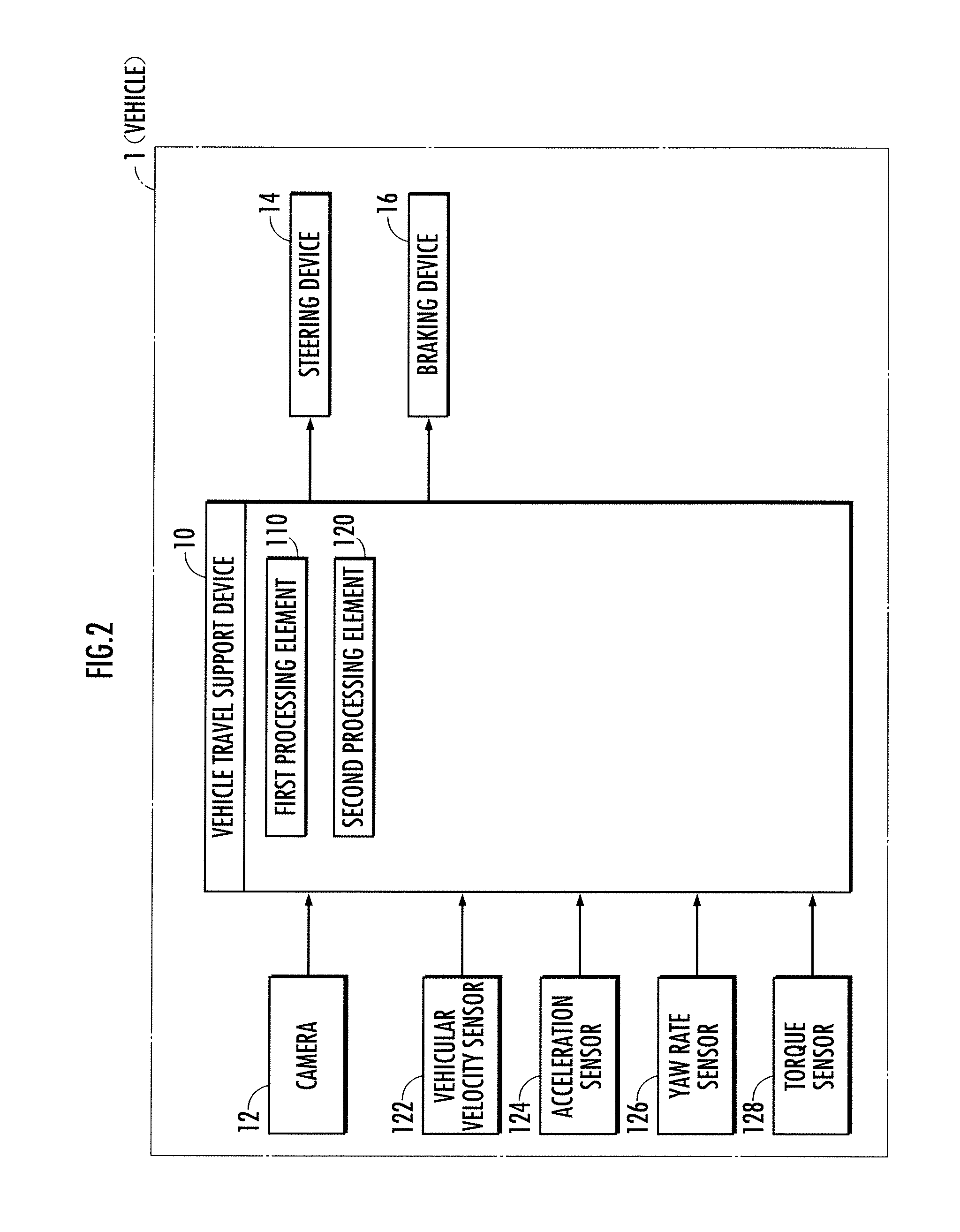
[0026]A vehicle (four-wheeled automobile) illustrated in FIG. 1 and FIG. 2 is mounted with a camera (imaging device) 12 such as a CCD camera, a CMOS image sensor or a near infrared camera, and a vehicle travel support device 10. The camera 12 is fixed in the vehicular compartment to photograph the front side of the vehicle 1 through the windshield. The vehicle 1, as illustrated in FIG. 2, is further disposed with sensors such as a vehicular velocity sensor 122, an acceleration sensor 124, a yaw rate sensor 126 and a torque sensor 128, a steering device 14 and a braking device 16. The vehicular velocity sensor 122, the acceleration sensor 124 and the yaw rate sensor 126 output signals related to a vehicular velocity, an acceleration and a yaw rate of the vehicle 1, respectively. As disclosed in Japanese Patent Laid-open No. 2003-15496...


PUM


Abstract

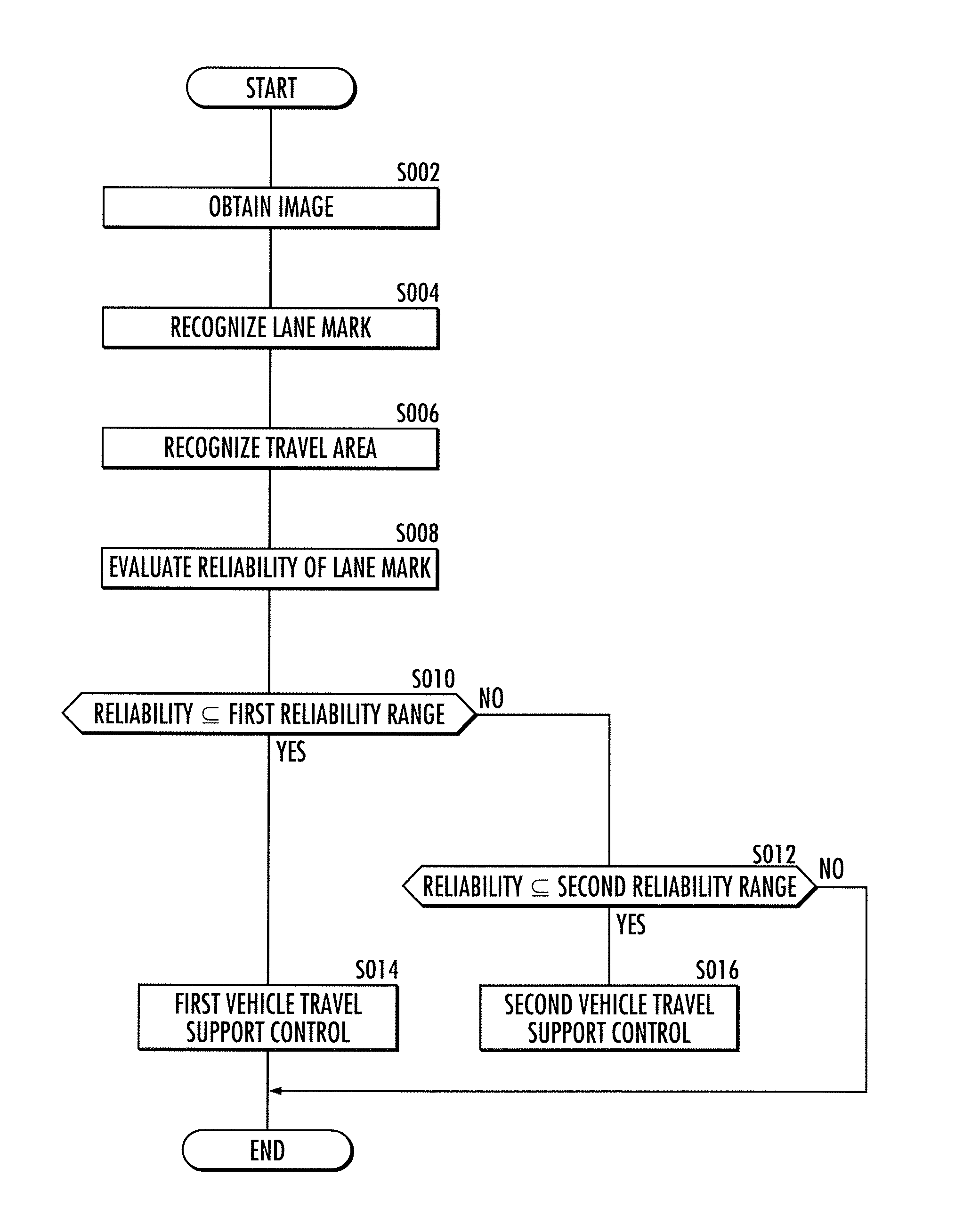
A vehicle travel support device capable of continuing operation even when the recognition accuracy of a lane mark has been degraded, and the like, wherein the degree of control on the operation of a steering device or the like is set higher as the reliability of a lane mark becomes higher. In a state in which the reliability of a travel area demarcated by the lane mark is high, a vehicle's travel is relatively strongly or actively supported so that the vehicle will not depart from the travel area. On the other hand, the degree of control on the operation of the steering device or the like is set lower as the reliability of the lane mark is lower. In a state in which the reliability of the travel area demarcated by the lane mark is low, the vehicle's travel is relatively weakly or passively supported so that the vehicle will not depart from the travel area.

Description

CROSS-REFERENCE TO RELATED APPLICATIONS[0001]The present invention is the US National Phase of International Application No. PCT / JP2009 / 000073 filed 9 Jan. 2009, which claims priority under 35 USC 119 based on Japanese patent application No. 2008-062278 filed on 12 Mar. 2008. The entire subject matter of these priority documents is incorporated by reference herein.BACKGROUND OF THE INVENTION[0002]1. Field of the Invention[0003]The present invention relates to a device supporting a vehicle in travelling according to an image obtained through an imaging device mounted in the vehicle, and the like.[0004]2. Description of the Related Art[0005]There has been disclosed an art (refer to Japanese Patent Laid-open No. 2001-023094) in which a disposition of a lane mark such as a traffic lane or a raised road marker provided on a road where a vehicle is travelling according to an image photographed by a camera mounted in the vehicle is recognized. There has also been disclosed an art which con...

Claims


Application Information

Patent Timeline
Patent Type & Authority Patents(United States)
IPC IPC(8): A01B69/00B60R21/00B60T8/17B60W10/00B60W10/18B60W10/184B60W10/20B60W30/00B60W30/12B62D6/00B62D101/00B62D103/00B62D119/00B62D137/00
CPCB60T8/17557B62D15/025G08G1/16B60T2201/08B60T2201/083B60T2201/087B60W10/18B60W10/20B60W30/18172B60W50/08B60W2050/146B60W2520/10G08G1/167B60W2540/18
Inventor KOBAYASHI, SACHIO
Owner HONDA MOTOR CO LTD
Learn More