Tubular fuel cell and fuel cell module

a fuel cell and tube-type technology, applied in the manufacture of cell components, cell component details, final product manufacturing, etc., can solve the problems of obstructing the efforts to miniaturize the fuel cell module, affecting the production of inexpensive fuel cell modules, and complicated connections of current collecting wires, so as to achieve a simple and less expensive manufacturing of spacers.

Active Publication Date: 2012-11-13
TOYOTA JIDOSHA KK
View PDF22 Cites 0 Cited by
  • Summary
  • Abstract
  • Description
  • Claims
  • Application Information

AI Technical Summary

Benefits of technology

[0011]Because conductivity is imparted to the spacer, when a plurality of tubular fuel cells are combined into a module, the spacer is capable of concurrently functioning to maintain a predetermined spacing between the tubular fuel cells and to provide electrical connection between the tubular fuel cells. Accordingly, inexpensive manufacturing of the fuel cell module can be realized.
[0013]Alternatively, a part of the exterior coil may be wound so as to have an outside diameter larger than that of other parts of the exterior coil and may be used as a spacer, which can again contribute to simpler, less expensive manufacturing of the spacer.

Problems solved by technology

Such a system of connecting the current collecting wires is complicated, hampering production of inexpensive fuel cell modules.
Further, there has been a necessity to provide electrodes for current collection in addition to the spacers, which obstructs efforts to miniaturize the fuel cell module.
In particular, when several to tens of thousands of ultra-thin tubular fuel cells measuring approximately several millimeters in diameter are assembled and combined into a module while securing a several millimeter cell spacing, electrical connection between the cells combined into the module should be established, which necessitates a highly accurate wiring technique and a great amount of time and effort.
Accordingly, the resulting operation or process of manufacturing a fuel cell module is complicated and difficult, thereby increasing manufacturing costs.

Method used


Image

  • Tubular fuel cell and fuel cell module
  • Tubular fuel cell and fuel cell module
  • Tubular fuel cell and fuel cell module

Examples


example modification

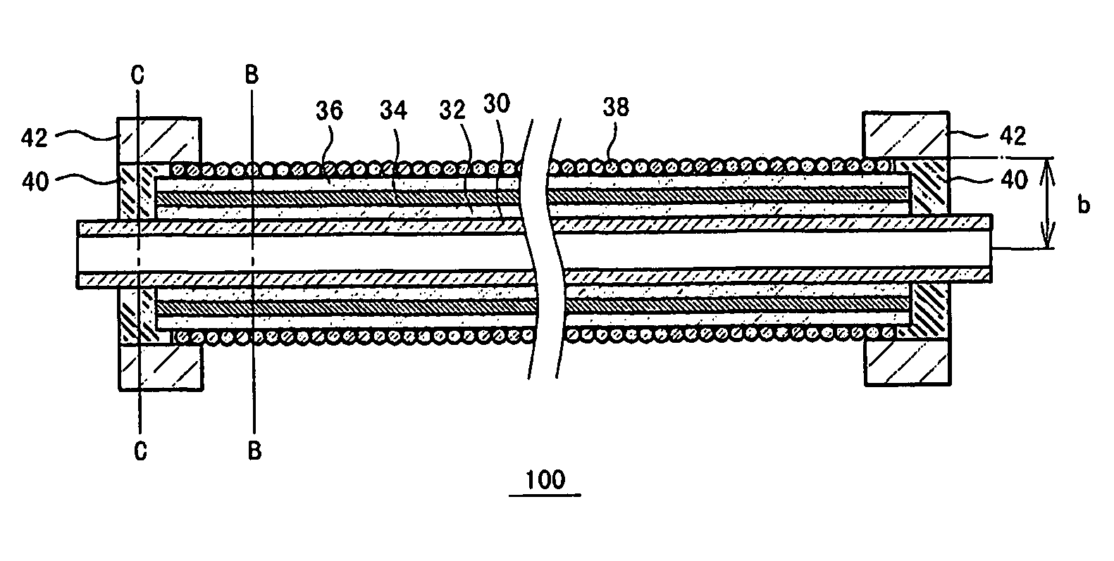
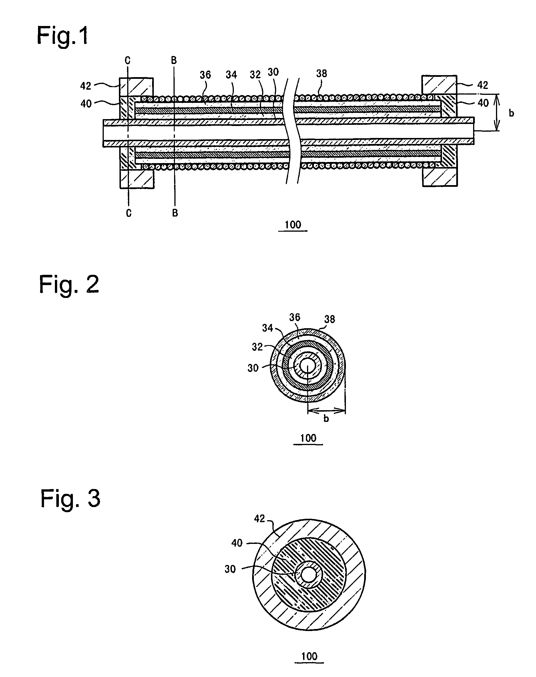
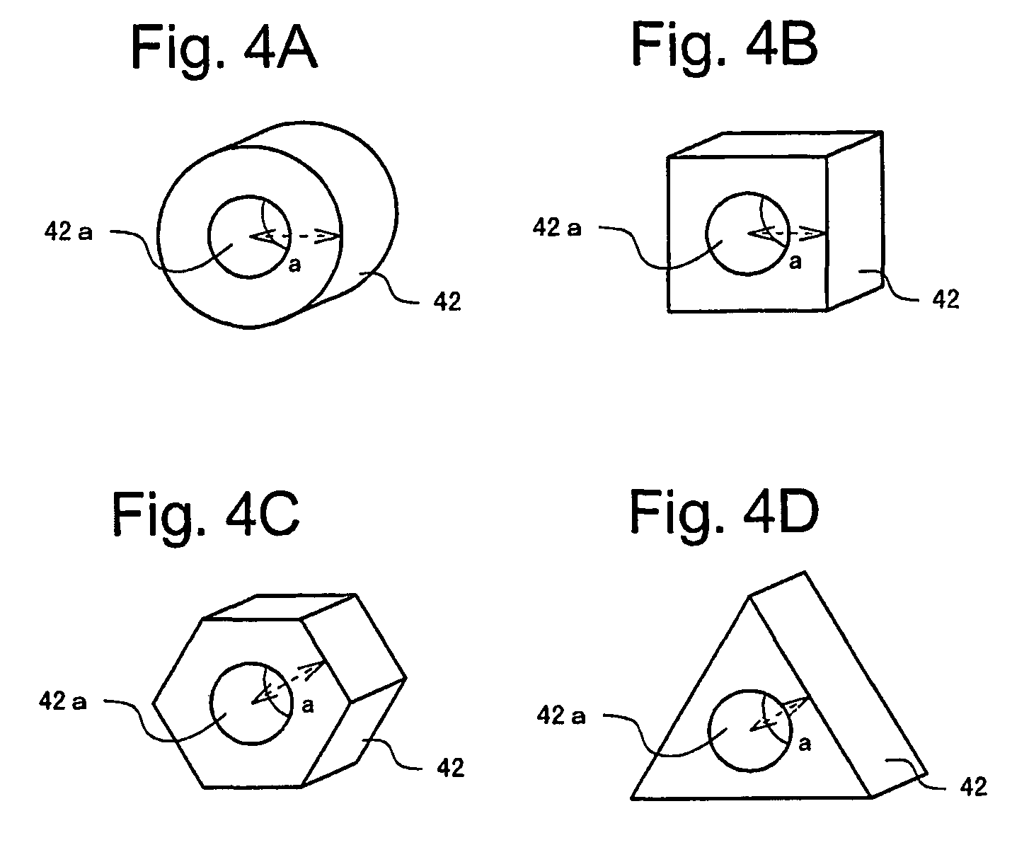
[0054]FIGS. 6 and 7 show, in cross sectional view, tubular fuel cells 102 and 104 according to modified examples of the present embodiment. In the modified examples, a part of the exterior coil 38 is wound so as to have an outside diameter a greater than the outside diameter b of the other part of the exterior coil 38 wound around the outer circumferential surface of the second catalytic layer 36, thereby defining the part of the exterior coil 38 as the spacer 42. For example, as shown in FIGS. 6 and 7, each end of the exterior coil 38 wound around the outer circumferential surface of the second catalytic layer 36 may be extended and wound around the outer circumferential surface of the resin seal 40, to configure the end of the exterior coil 38 as the spacer 42.

[0055]Here, in a case where the outside diameter of the resin seal 40 is equal to that of the second catalytic layer 36 as shown in FIG. 6, when the exterior coil 38 is wound around the outer circumferential surface of the s...


PUM

PropertyMeasurementUnit
diameteraaaaaaaaaa
diameteraaaaaaaaaa
radiusaaaaaaaaaa

Abstract

A tubular fuel cell comprises a cylindrical internal electrode having electrical conductivity, a lamination of a first catalytic layer, an electrolytic layer, and a second catalytic layer laminated in that order on an outer circumferential surface of the internal electrode, and an electrically conductive exterior coil wound around an outer circumferential surface of the second catalytic layer. The tubular fuel cell further comprises an electrically conductive spacer which has an outside diameter greater than that of the exterior coil.

Description

CROSS-REFERENCE TO PRIOR APPLICATION[0001]This is the U.S. National Phase Application under 35 U.S.C. §371 of International Patent Application No. PCT / JP2006 / 315776, filed Aug. 3, 2006, which claims benefit of Japanese Patent Application No. 2005-231764, filed Aug. 10, 2005.TECHNICAL FIELD[0002]The present invention relates to a tubular fuel cell and a fuel cell module in which a current collecting electrode also functions as a spacer between fuel cells.BACKGROUND ART[0003]As shown in a cross sectional view of FIG. 8 taken along a tube drawing direction, a tubular fuel cell is conventionally configured to include an internal electrode 10, a first catalytic layer 12, an electrolytic layer 14, a second catalytic layer 16, an exterior coil 18, and a resin seal 20. FIG. 9 is a cross sectional view taken along a line A-A in FIG. 8. As shown in FIG. 9, the internal electrode 10, the first catalytic layer 12, the electrolytic layer 14, and the second catalytic layer 16 are sequentially lam...

Claims


Application Information

Patent Timeline
Patent Type & Authority Patents(United States)
IPC IPC(8): H01M8/10H01M8/24H01M2/20
CPCH01M8/0252H01M8/2465H01M8/247H01M2008/1095Y02E60/50Y02P70/50H01M8/2485
Inventor TERADA, MASAKIKATAYAMA, YUKIHISAISHIMARU, HIROKAZUHAMA, YUICHIRO
Owner TOYOTA JIDOSHA KK
Why Eureka
Try Eureka