Touch panel display apparatus, electronic device having touch panel display apparatus, and camera having touch panel display apparatus

a touch panel display and electronic device technology, applied in the field of touch panel display apparatus, can solve the problems of increasing power consumption, difficult to obtain uniform vibration by using one actuator, and difficult to reduce the thickness of the apparatus, so as to achieve easy reduction in size, thickness and weight, and small drive force

Active Publication Date: 2012-11-13
SONY CORP
View PDF23 Cites 76 Cited by
  • Summary
  • Abstract
  • Description
  • Claims
  • Application Information

AI Technical Summary

Benefits of technology

[0008]Thus, it is desirable to provide a touch panel display apparatuses configured as to generate a tactile sensation on the user's fingertip operating the display, which can be easily reduced in size, thickness and weight, which consumes less electric power, which does not need a large number of actuators, and which has also the function as an acoustic output device.
[0012]According to an embodiment the present invention, in order to generate a tactile sensation on a user's fingertip making contact with a panel surface, a movable panel unit is vibrated not in the direction perpendicular to the panel surface but along a plane parallel to the panel surface. Therefore, the movable panel unit can be vibrated by a small-type actuator having a small drive force, while obviating vibration of air at the panel surface. Accordingly, a touch panel display apparatuses configured as to generate a tactile sensation on a user's fingertip operating the display can be realized which can be easily reduced in size, thickness and weight, which consumes less electric power, which does not need a large number of actuators, and which has also the function as an acoustic output device.

Problems solved by technology

However, in the touch panel display apparatus disclosed in Japanese Patent Laid-open No. 2003-288158, an actuator for generating a vibration should be displayed between the touch panel and a display panel, between the display panel and a backlight, or between the backlight and a frame, which makes it difficult to reduce the thickness of the apparatus.
However, for vibrating a liquid crystal display panel, for example, in a direction perpendicular to the panel surface, a quite large drive force may be necessary, which leads to an increase in power consumption.
In addition, at the time of vibrating a liquid crystal display panel in a direction perpendicular to the panel surface thereof, a ribbon cable connected to the liquid crystal display panel generates an asymmetric resisting force, which makes it difficult to obtain a uniform vibration by using one actuator.
The difficulty in obtaining a uniform vibration means difficulty in realizing a display panel having also the function as an acoustic output device.

Method used


Image

  • Touch panel display apparatus, electronic device having touch panel display apparatus, and camera having touch panel display apparatus
  • Touch panel display apparatus, electronic device having touch panel display apparatus, and camera having touch panel display apparatus
  • Touch panel display apparatus, electronic device having touch panel display apparatus, and camera having touch panel display apparatus

Examples


Embodiment Construction

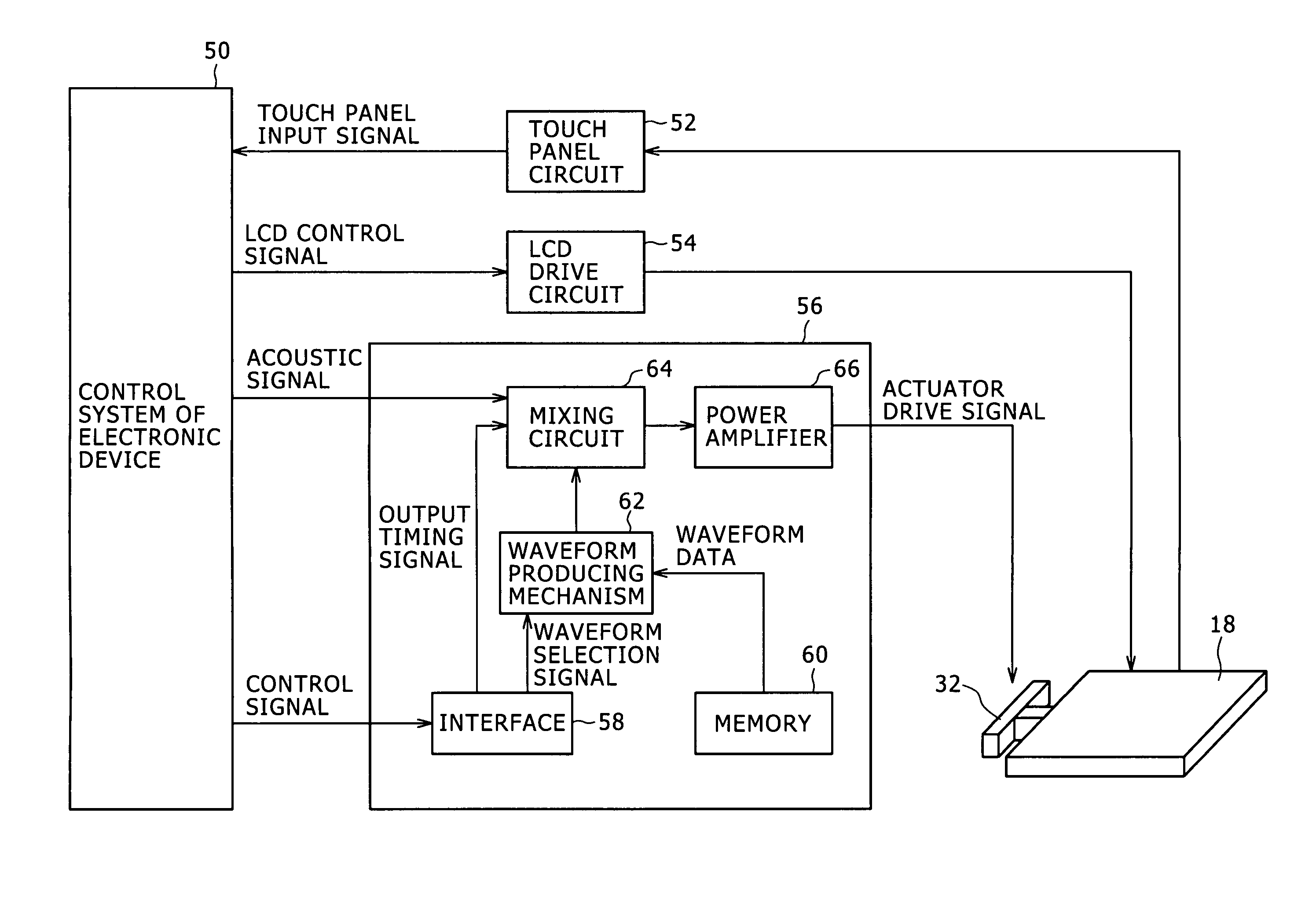
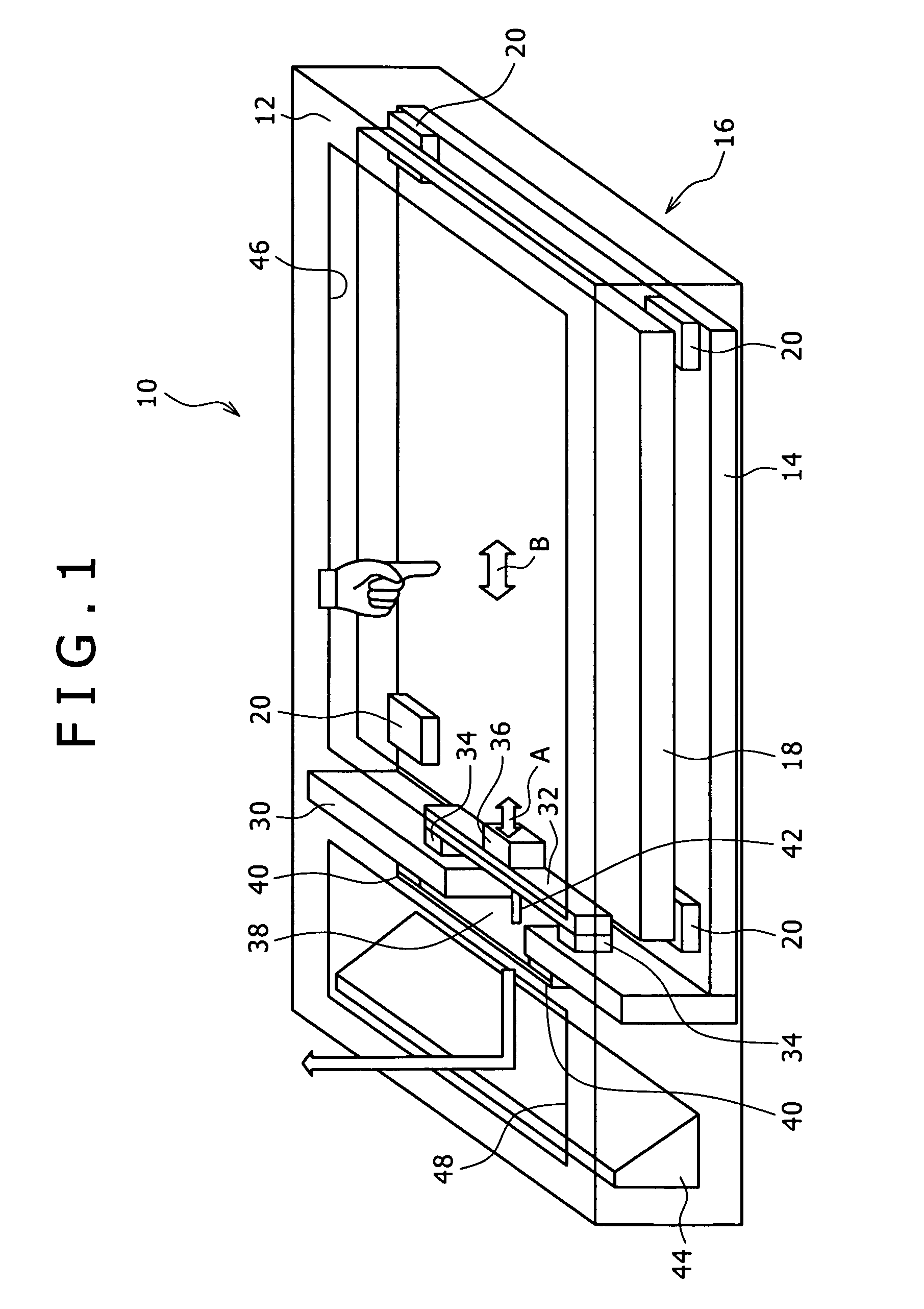
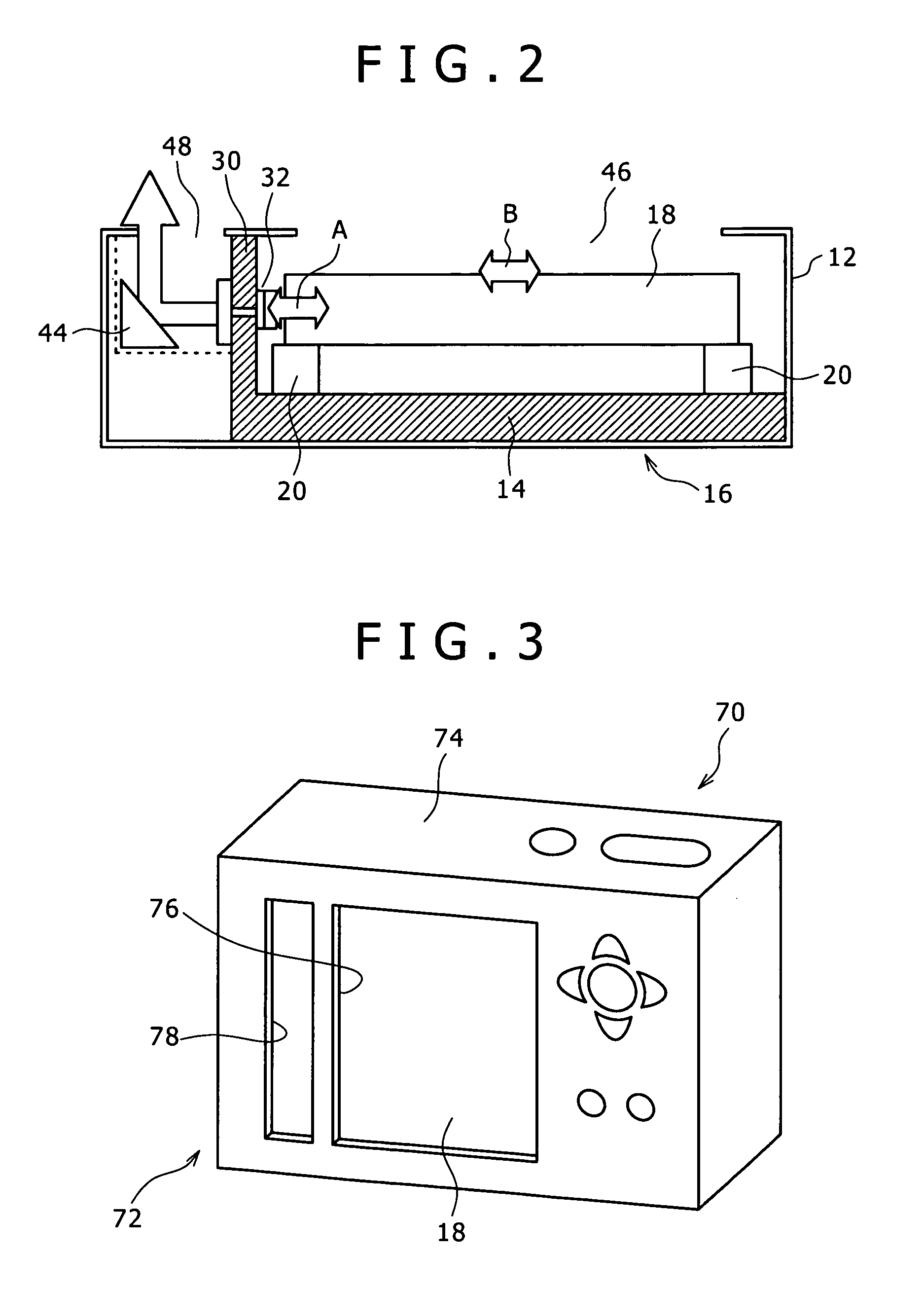
[0019]Now, some embodiments of the present invention will be described below. FIG. 1 is a schematic perspective view of a touch panel display apparatus according to an embodiment of the present invention, and FIG. 2 is a schematic side view of the same. These figures are schematic views for making clear the principle of the present invention, and, in the figures, the length-to-thickness ratios and the like of members and the shapes of the members are not drawn properly. FIG. 3 is a perspective view showing the back side of a camera having a still picture shooting function and a motion picture shooting function, which is an electronic device according to an embodiment of the present invention. The camera shown in FIG. 3 has a casing or frame and a monitor, and the monitor includes the touch panel display apparatus shown in FIGS. 1 and 2. Incidentally, the touch panel display apparatus shown in FIGS. 1 and 2 are used as the monitor in the camera and also widely used as an input device...


PUM


Abstract

Disclosed herein is a touch panel display apparatus including: a display panel; a movable panel unit including a touch panel and being flat plate-like in shape; a movable support section for supporting the movable panel unit on a support structure so as to permit the movable panel unit to be moved along a plane parallel to the panel surface of the movable panel unit; an actuator configured to drive the movable panel unit to vibrate; an actuator drive control section for outputting an actuator drive signal to drivingly control the actuator; an acoustic pressure generating member configured to generate an acoustic pressure by being driven by the actuator to vibrate; and a superposing section for superposing an acoustic signal on the actuator drive signal outputted by the actuator drive control section.

Description

CROSS REFERENCES TO RELATED APPLICATIONS[0001]The present invention contains subject matter related to Japanese Patent Application JP 2005-220845 filed in the Japanese Patent Office on Jul. 29, 2005, the entire contents of which being incorporated herein by reference.BACKGROUND OF THE INVENTION[0002]1. Field of the Invention[0003]The present invention relates to a touch panel display apparatus, an electronic device having a touch panel display apparatus, and a camera having a touch panel display apparatus.[0004]2. Description of the Related Art[0005]Touch panel display apparatuses used as an input device or an input / output device have such a flexibility as not to be obtainable with input devices using mechanical switched, since the input screen of a touch panel display apparatus can be freely configured by software. In addition, the touch panel display apparatuses have a number of merits such as lightweight and compact configurations obtainable and a low frequency of occurrence of m...

Claims


Application Information

Patent Timeline
Patent Type & Authority Patents(United States)
IPC IPC(8): G09G5/00
CPCG06F3/016G06F3/041G06F3/0416H04N5/2251H04N5/23293
Inventor TAKENAKA, MIKIOMARUYAMA, SHIGEAKISEKINE, JUNICHI
Owner SONY CORP
Why Eureka
Try Eureka