Electronic tuner and high frequency receiving device using the same

a technology of high frequency receiving device and electronic tuner, which is applied in the direction of amplitude demodulation, dc level restoring means or bias distort correction, and baseband system details, etc., can solve the problem of large power consumption and achieve the effect of less power consumption

Inactive Publication Date: 2012-11-13
PANASONIC CORP
View PDF4 Cites 8 Cited by
  • Summary
  • Abstract
  • Description
  • Claims
  • Application Information

AI Technical Summary

Benefits of technology

[0015]The present invention offers a high-frequency receiver that consumes less power.
[0016]In the high-frequency receiver of the present invention, a demodulator includes a reception quality evaluation circuit for evaluating the quality of received signal by comparison with a first reference value and outputting an evaluation signal, and a driving circuit receiving this evaluation signal. If the reception quality evaluation circuit evaluates that the quality of received signal is acceptable, a power supply to a DC offset control loop is stopped by the driving circuit. This achieves the high-frequency receiver that consumes less power.
[0017]In an electronic tuner of the present invention, a demodulator includes a reception quality detecting circuit for detecting the quality of received signal, a first fading detecting circuit for detecting fading frequency due to movement, a reception quality evaluation circuit receiving a reception quality signal from the reception quality detecting circuit and the fading frequency from the first fading detecting circuit, and a driving circuit receiving a reception quality evaluation signal output from this reception quality evaluation circuit and supplying or stopping power to a DC offset control loop. A quality evaluation reference value in the reception quality evaluation circuit is set according to the fading frequency from the first fading detecting circuit. If the reception quality evaluation circuit evaluates that the quality of received signal is acceptable, a power supply to the DC offset control loop is stopped by the driving circuit. This achieves the high-frequency receiver that consumes less power.
[0018]Furthermore, an electronic tuner of the present invention includes a driving circuit receiving a first evaluation signal output from a DC offset evaluation circuit. A first driving voltage output from this driving circuit is connected to a DC offset correcting circuit. The driving circuit stops power supply to the DC offset correcting circuit if the DC offset evaluation circuit evaluates that the first and second DC offset voltages are less than a reference value. This achieves the electronic tuner that consumes less power.

Problems solved by technology

This results in large power consumption.Patent Literature 1: Japanese Patent Unexamined Publication No. 2003-134183

Method used


Image

  • Electronic tuner and high frequency receiving device using the same
  • Electronic tuner and high frequency receiving device using the same
  • Electronic tuner and high frequency receiving device using the same

Examples


first exemplary embodiment

[0057]A high-frequency receiver in the first exemplary embodiment of the present invention is described below with reference to drawings.

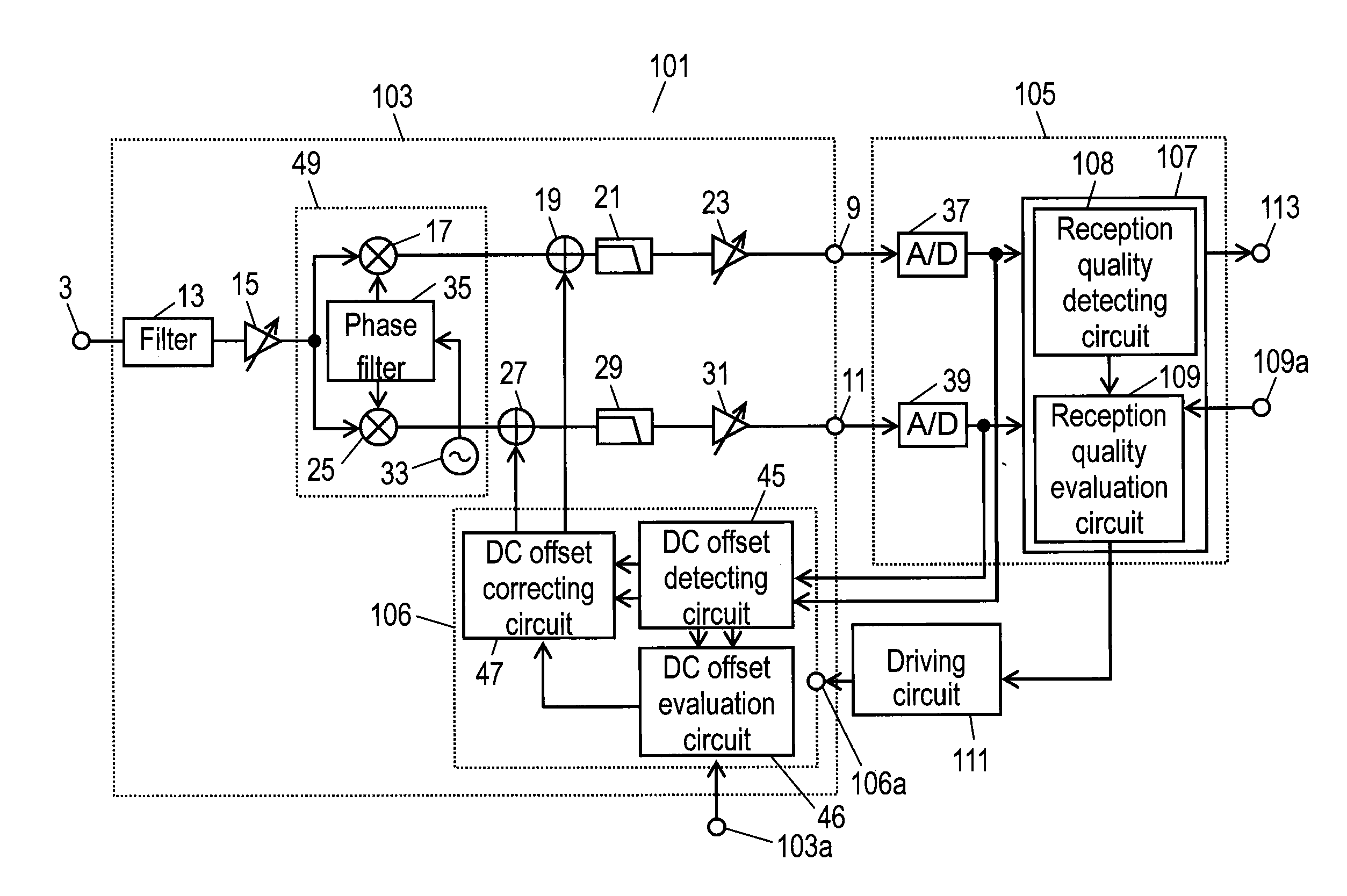
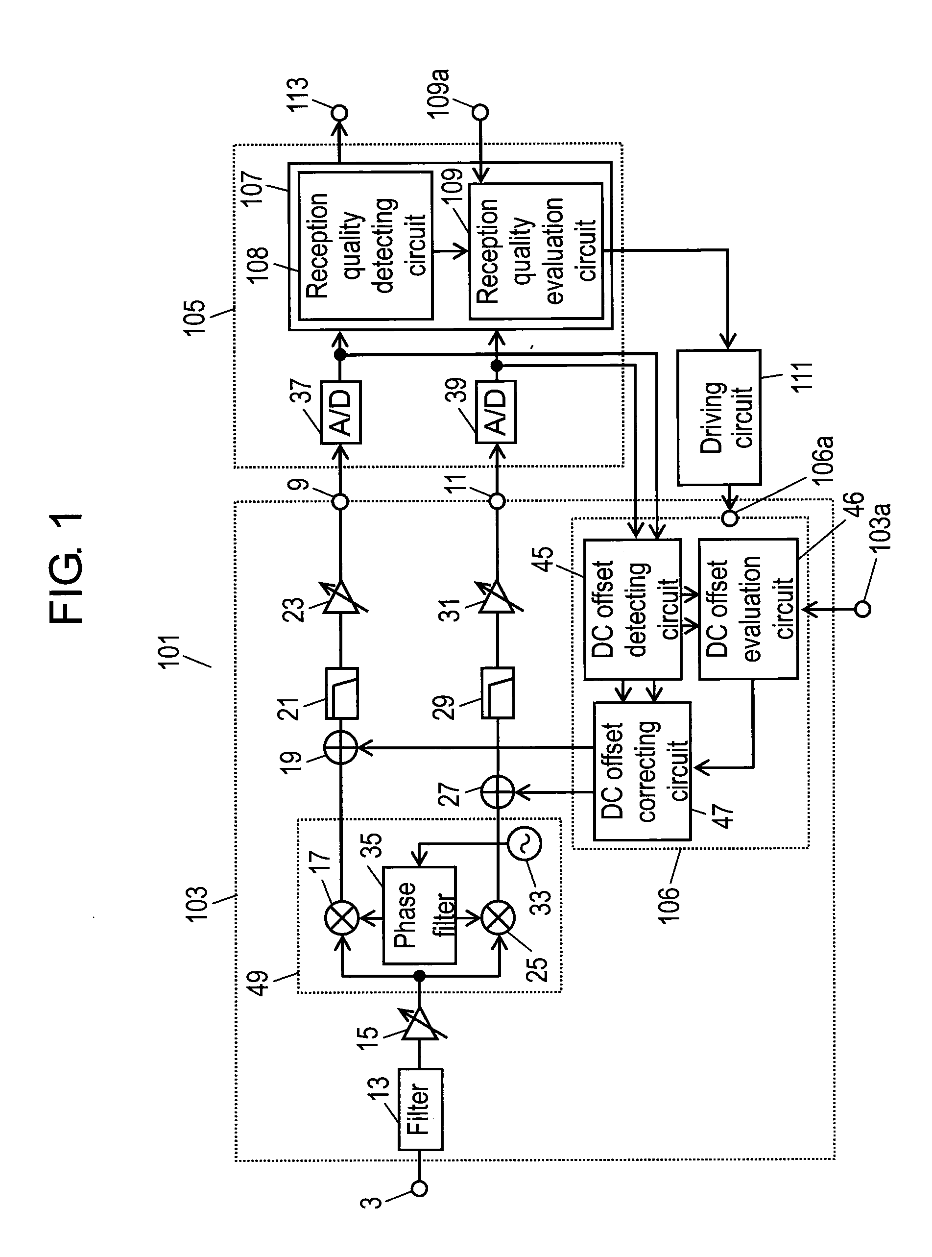
[0058]FIG. 1 is a circuit block diagram of the high-frequency receiver in the first exemplary embodiment of the present invention.

[0059]In FIG. 1, components same as those in the prior art shown in FIG. 17 are given the same reference marks.

[0060]High-frequency receiver 101 includes input terminal 3 connected to an antenna, electronic tuner 103 for selecting a desired channel from received signals input from this input terminal 3, and demodulator 105 for demodulating I and Q signals output from this electronic tuner 103.

[0061]This electronic tuner 103 includes filter 13 for passing received signals from input terminal 3, amplifier 15 receiving an output of this filter 13, mixers 17 and 25 receiving an output of this amplifier through their one inputs, oscillator 33 connected to the other inputs of these mixers 17 and 25 via phase shifter 35, compos...

second exemplary embodiment

[0098]Next, a high-frequency receiver in the second exemplary embodiment of the present invention is described with reference to drawings.

[0099]FIG. 4 is a circuit block diagram of high-frequency receiver 141 in the second exemplary embodiment. In FIG. 4, a circuit block configuration of high-frequency receiver 141 is basically the same as that of high-frequency receiver 101 in the first exemplary embodiment. A difference between high-frequency receiver 141 in the second exemplary embodiment and high-frequency receiver 101 in the first exemplary embodiment is a method of correcting the first and second DC offset voltages. This is described below.

[0100]High-frequency receiver 141 includes input terminal 3 connected to an antenna, electronic tuner 103 for selecting a desired channel from received signals input from this input terminal 3, and demodulator 105 for demodulating I and Q signals output from this electronic tuner 103.

[0101]This electronic tuner 103 includes filter 13 for pas...

third exemplary embodiment

[0141]High-frequency receiver 201 in the third exemplary embodiment is described below with reference to drawings.

[0142]FIG. 7 is a circuit block diagram of high-frequency receiver 201 in the third exemplary embodiment of the present invention. Compared to high-frequency receiver 101 in the first exemplary embodiment, demodulator 202 in high-frequency receiver 201 in this exemplary embodiment includes waveform equivalent circuit unit 208 between Fast Fourier Transformer (FFT) 205 forming a demodulating circuit and detecting circuit 207, so as to correct signal degradation due to fading. In addition, fading detecting circuit 211 is connected between this waveform equivalent circuit unit 208 and reception quality evaluation circuit 210. These points are different. Compositors 19 and 27 may retain the first and second cancel signals, respectively, instead of continuously supplying cancel signals without changing values from DC offset correcting circuit 47 to compositors 19 and 27.

[0143...


PUM


Abstract

Demodulator includes reception quality evaluation circuit for evaluating the quality of a received signal by comparison with a first reference value, and outputting an evaluation signal; and driving circuit receiving the evaluation signal. If reception quality evaluation circuit evaluates that the quality of the received signal is acceptable, power supply from driving circuit to DC offset control loop is stopped. This offers a high-frequency receiver that reduces power consumption.

Description

[0001]THIS APPLICATION IS A U.S. NATIONAL PHASE APPLICATION OF PCT INTERNATIONAL APPLICATION PCT / JP2008 / 003910.TECHNICAL FIELD[0002]The present invention relates to high-frequency receivers employing a direct conversion system electronic tuner used typically for battery-driven mobile televisions.BACKGROUND ART[0003]A conventional high-frequency receiver is described below with reference to drawings.[0004]FIG. 17 is a circuit block diagram of conventional high-frequency receiver 1. In FIG. 17, conventional high-frequency receiver 1 includes input terminal 3 connected to an antenna, electronic tuner 5 for selecting a desired channel from received signals input from this input terminal 3, and demodulator 7 for demodulating I and Q signals output from this electronic tuner 5.[0005]This electronic tuner 5 includes filter 13 passing the received signals from input terminal 3, amplifier 15 receiving an output of this filter 13, mixers 17 and 25 receiving an output of this amplifier through...

Claims


Application Information

Patent Timeline
Patent Type & Authority Patents(United States)
IPC IPC(8): H04L25/06
CPCH04B1/30H04L25/067H04L27/2647H04L25/0224H04L2027/004
Inventor UMEDA, TAKASHIOZEKI, HIROAKIFUJISHIMA, AKIRA
Owner PANASONIC CORP
Why Eureka
Try Eureka