Method of manufacturing a disk drive having a base member, bearing unit, drive unit and hub

a technology of disk drives and base members, which is applied in the direction of casings/cabinets/drawers, instruments, casings/cabinets/drawers, etc., can solve the problems of thermal asperity failure, ta failure, or a head crash failure in the magnetic head, and interfere with the correct reading of the reproduced signal

Inactive Publication Date: 2012-11-20
SAMSUNG ELECTRO MECHANICS JAPAN ADVANCED TECHNOLOGY CO LTD
View PDF6 Cites 6 Cited by
  • Summary
  • Abstract
  • Description
  • Claims
  • Application Information

AI Technical Summary

Benefits of technology

[0009]The present invention has been made in view of the aforementioned circumstances, and a purpose of the invention is to provide a technique in which a cleanness level inside a disk drive device is improved such that an incidence of a TA failure can be maintained at a low level in the case where a gap between a magnetic head and a recording disk is small while the magnetic head is tracing the recording disk.
[0011]According to the embodiment, the number of particles attaching to the disk drive device while the device is being manufactured, can be reduced.
[0013]According to the embodiment, a disk drive device having the reduced number of particles attaching thereto while the device is being manufactured, can be provided.

Problems solved by technology

On the other hand, the use of the MR element in such a small gap causes a fear that a thermal asperity failure (hereinafter, referred to as a TA failure) or a head crash failure may occur in the magnetic head.
Specifically, the TA failure means that: minor foreign substances on the surface of the recording disk are in contact with the MR element while the magnetic head is floating to trace the recording tracks, and therefore heat is momentarily caused in the MR element due to kinetic energy of the foreign substances; and a resistance value of the MR element is momentarily varied due to momentary heating or cooling of the MR element, resulting in superimposition of the varied resistance value on a reproduced signal as a noise, and interference with correct reading of the reproduced signal.
Even when the base is cleaned, however, particles possibly attach thereto in a step of fixing a bearing unit and a hub to the base.
In the second case, when an adhesive is used for fixing the bearing unit and the hub to the base, a component included in the adhesive may fly in all directions and attach to the surfaces of the bearing unit and the hub, causing particles attaching thereto.
As stated above, the particles attaching thereto while fixing parts, cannot be removed by a conventional method of manufacturing a disk drive device, and hence a cleanness level inside a general disk drive device is low.
Remaining of many particles causes a high incidence of the TA failure when the gap in which the magnetic head floats becomes small, resulting in interference with miniaturization and increased capacity of the disk drive device.

Method used


Image

  • Method of manufacturing a disk drive having a base member, bearing unit, drive unit and hub
  • Method of manufacturing a disk drive having a base member, bearing unit, drive unit and hub
  • Method of manufacturing a disk drive having a base member, bearing unit, drive unit and hub

Examples


Embodiment Construction

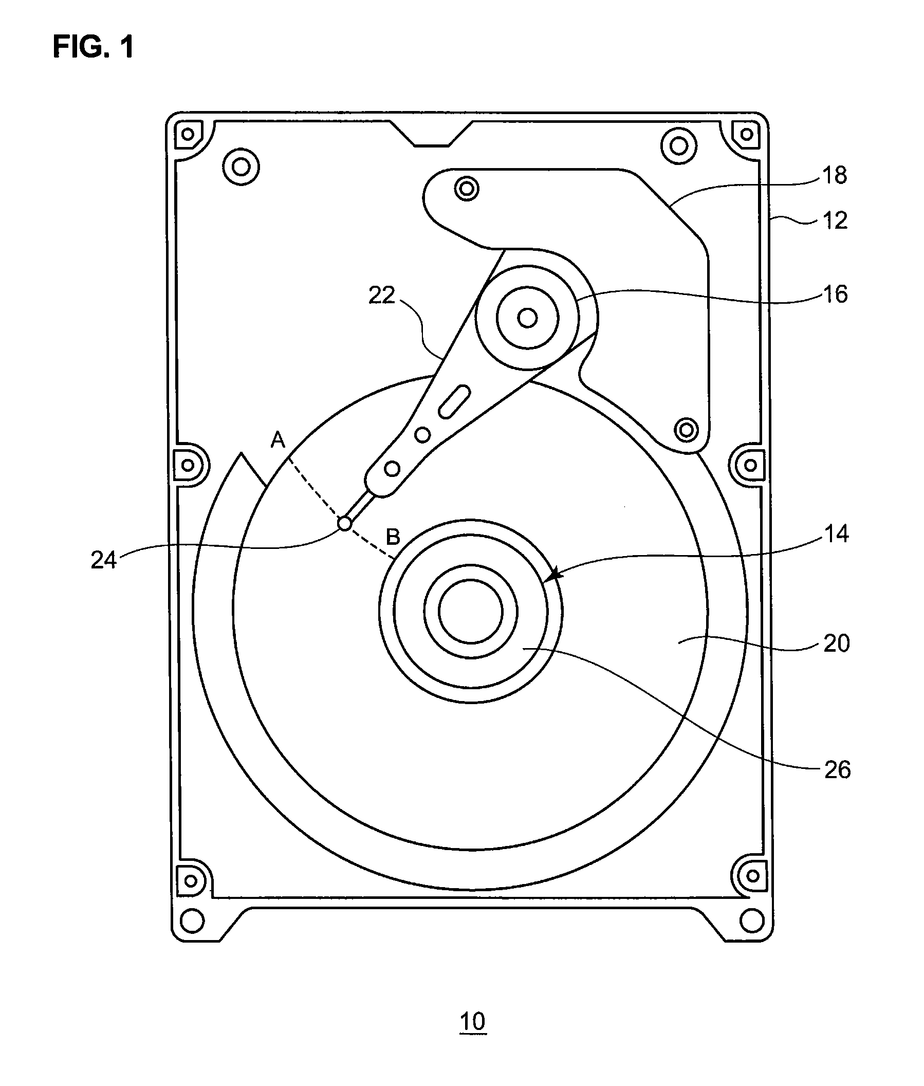
[0025]The invention will now be described by reference to the preferred embodiments. This does not intend to limit the scope of the present invention, but to exemplify the invention. FIG. 1 is a top view of a disk drive device 10 assembled by using a method of manufacturing a disk drive device 10 according to an embodiment. FIG. 1 illustrates a state where a top cover is removed to expose an internal structure. In the drawing, an HDD is illustrated as an example of the disk drive device 10.

[0026]The disk drive device 10 comprises a base member 12, a drive unit 14, an arm bearing unit 16, a voice coil motor 18, a recording disk 20, a swing arm 22, a magnetic head 24 and a hub 26. The drive unit 14, the arm bearing unit 16 and the voice coil motor 18, etc., are mounted on the top surface of the base member 12. The recording disk 20 can magnetically store data. The recording disk 20 is mounted on the hub 26.

[0027]The drive unit 14 supports the hub 26 to rotatably drive the recording di...


PUM

PropertyMeasurementUnit
sizesaaaaaaaaaa
temperatureaaaaaaaaaa

Abstract

A method of manufacturing a disk drive device including: assembling a subassembly by fixing at least a bearing unit, a drive unit and a hub to a base member in a first clean room; cleaning the subassembly in a second clean room; and sealing the subassembly by a sealing member. The first clean room and the second clean room are communicated with each other by a communicating opening for transferring the subassembly, and an atmospheric pressure in the second clean room is equal to or higher than that in the first clean room.

Description

BACKGROUND OF THE INVENTION[0001]1. Field of the Invention[0002]The present invention relates to a method of manufacturing a disk drive device and a disk drive device manufactured by the method, and in particular, to a method of manufacturing a disk drive device to which a reduced amount of particles attaches and a disk drive device manufactured by the method.[0003]2. Description of the Related Art[0004]Recently, disk drive devices such as an HDD (Hard Disk Drive) have been required to be small in size and increased in capacity. For example, a disk drive device magnetically storing data rotates a recording disk having recording tracks at a high speed, so that a read / write operation of data is executed while a magnetic head of the device is floating above the recording tracks so as to maintain a slight gap between them. In order for such a disk drive device to be small in size and increased in capacity, a width of the recording track is required to be narrow. As the width of the reco...

Claims


Application Information

Patent Timeline
Patent Type & Authority Patents(United States)
IPC IPC(8): G11B5/41B08B9/30
CPCG11B19/2009Y10T29/53096Y10T29/49025Y10T29/49034
Inventor OMURA, YUJINISHIHARA, KENJI
Owner SAMSUNG ELECTRO MECHANICS JAPAN ADVANCED TECHNOLOGY CO LTD
Why Eureka
Try Eureka