Dual intake valve system with one deactivation valve and one multi-lift valve for swirl enhancement

a dual-ventilation, multi-lift technology, applied in valve arrangements, machines/engines, output power, etc., can solve the problems of high flow rate and unbalanced flow, and achieve the effect of improving in-cylinder air flow turbulence, strong swirling, and high flow ra

Active Publication Date: 2012-11-20
DELPHI TECH IP LTD
View PDF1 Cites 37 Cited by
  • Summary
  • Abstract
  • Description
  • Claims
  • Application Information

AI Technical Summary

Benefits of technology

[0009]To improve in-cylinder air flow turbulence, each intake valve can be selectively operated at a different lift height, thereby resulting in a higher flow rate of intake air or air / fuel mixture through one intake valve which generates strong swirl by unbalanced flow. In one example of operating dual intake valves of an engine cylinder at different lift heights, one intake valve is operated at high-lift while the other intake valve is operated at low-lift. In another example of operating dual intake valves at different lift heights, one intake valve is operated at high-lift while the other intake valve is deactivated. In yet another example of operating dual intake valves at different lift heights, one intake valve is operated at low-lift while the other intake valve is deactivated.

Problems solved by technology

To improve in-cylinder air flow turbulence, each intake valve can be selectively operated at a different lift height, thereby resulting in a higher flow rate of intake air or air / fuel mixture through one intake valve which generates strong swirl by unbalanced flow.

Method used


Image

  • Dual intake valve system with one deactivation valve and one multi-lift valve for swirl enhancement
  • Dual intake valve system with one deactivation valve and one multi-lift valve for swirl enhancement
  • Dual intake valve system with one deactivation valve and one multi-lift valve for swirl enhancement

Examples


Embodiment Construction

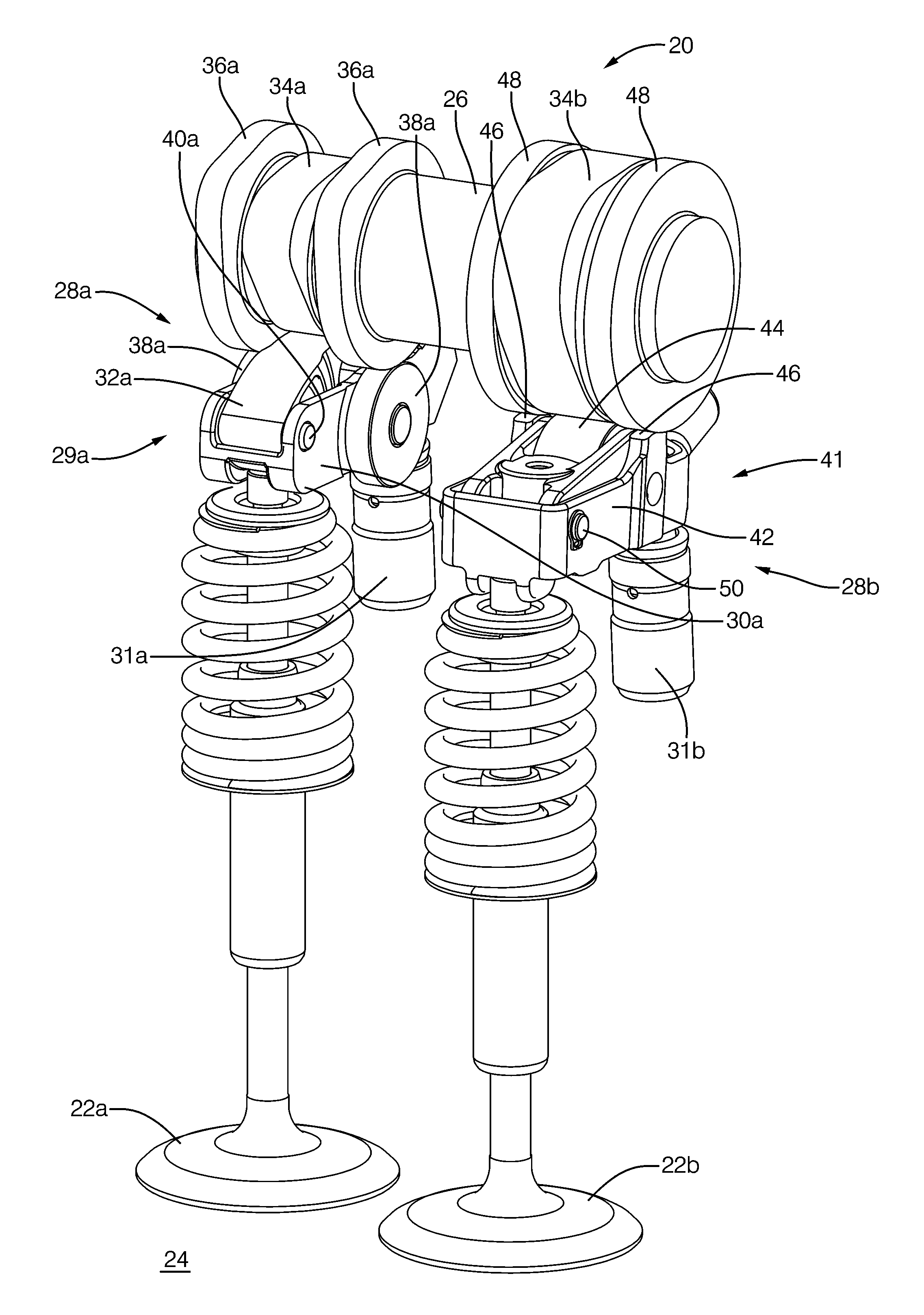
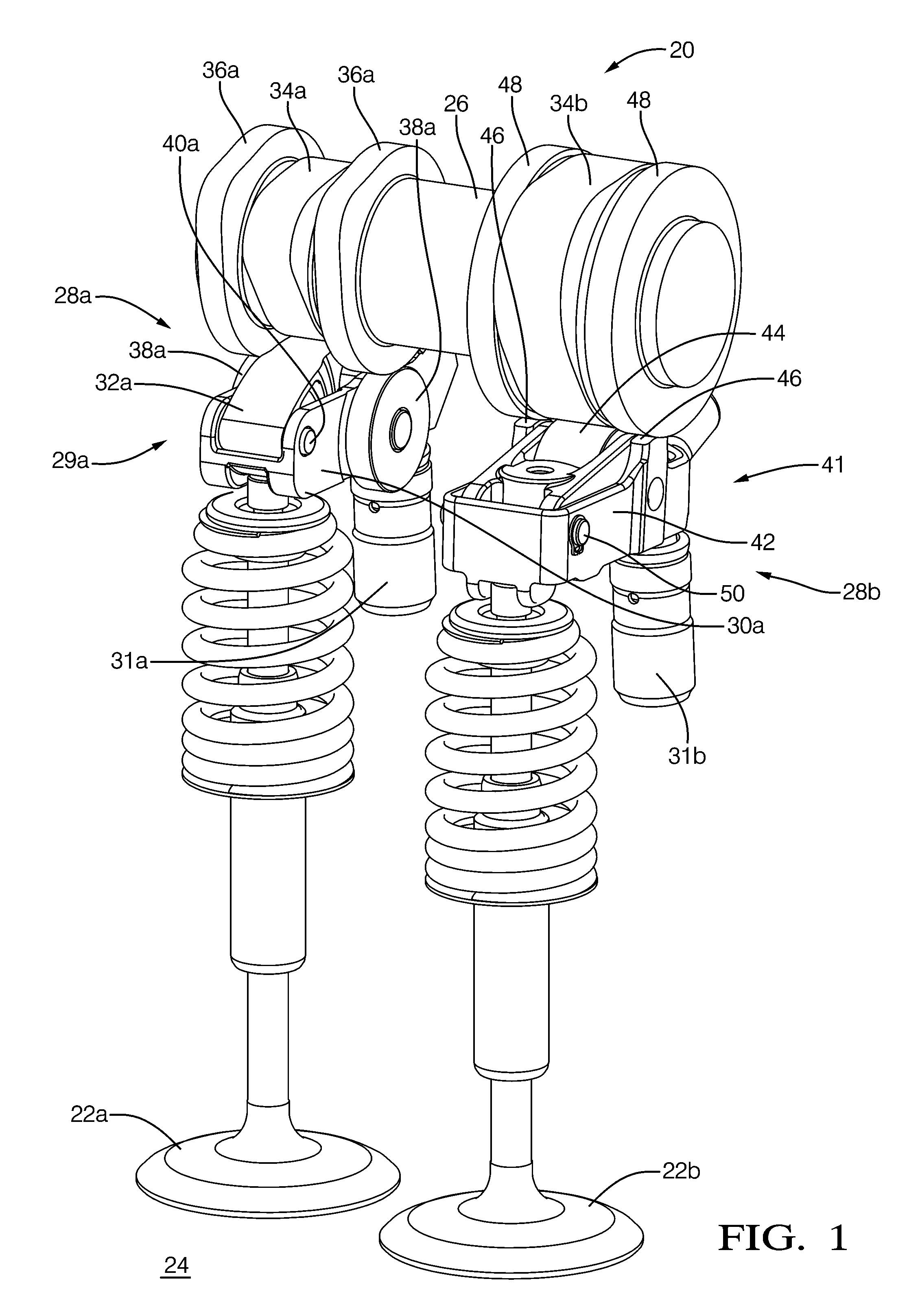
[0020]In accordance with a first preferred embodiment of the invention, FIG. 1 shows variable valve actuation system 20 for providing variable valve lift to first and second intake valves 22a, 22b which supply an air or air / fuel mixture to internal combustion engine 24. Internal combustion engine 24 may either be compression ignited or spark ignited. Rotational motion of engine camshaft 26 acts on first and second valve actuation means 28a, 28b for transmitting motion from engine camshaft 26 to first and second intake valves 22a, 22b respectively.

[0021]In the first preferred embodiment, first valve actuation means 28a includes first two-step actuation device 29a for selectively applying high-lift and low-lift to first intake valve 22a. The high-lift operational state is characterized by permitting first intake valve 22a to open to a maximum position while low-lift is characterized by permitting first intake valve 22a to open only to a position intermediate of the high-lift and valve...


PUM


Abstract

In a dual intake valve arrangement for an internal combustion engine, a variable valve lift system controls two intake valves for one or more engine cylinders. In each cylinder, one of the intake valves includes an associated two-step actuation device, and the other includes an associated valve deactivation device. To improve in-cylinder air flow turbulence, one valve may be operated in a high-lift or low-lift state while the other valve may be deactivated.

Description

TECHNICAL FIELD OF INVENTION[0001]The invention relates to variable valve lift systems for internal combustion engines; more particularly, to a system for variable valve lift of dual intake valves; and most particularly, to such a system wherein the valvetrain of one of the dual intake valves includes means for multi-lift positioning of that valve and the valvetrain of the other valve includes means for lost motion valve deactivation of that valve.BACKGROUND OF INVENTION[0002]Variable valve lift systems are known in the engine arts. See, for example, the systems disclosed in U.S. Pat. No. 6,668,779 and US Patent Application Publication No. 2008 / 0072855 published Mar. 27, 2008, the disclosures of which are both expressly incorporated herein by reference. Such systems typically incorporate a two-step roller finger follower to selectively transmit motion of either a high-lift cam lobe or a low-lift cam lobe of the engine's camshaft to an intake valve.[0003]Valve deactivation systems fo...

Claims


Application Information

Patent Timeline
Patent Type & Authority Patents(United States)
IPC IPC(8): F01L1/34
CPCF01L1/267F01L13/0005F01L13/0036F01L2800/06
Inventor ROE, RICHARD B.LEE, JONGMIN
Owner DELPHI TECH IP LTD
Why Eureka
Try Eureka