Fluid drainage device, delivery device, and associated methods of use and manufacture

a technology of fluid drainage device and delivery device, which is applied in medical science, surgery, diagnostics, etc., can solve the problems of ganglion cell death progressing in the retina, affecting the effect of vision, and limiting the visual field, so as to reduce the profile

Inactive Publication Date: 2012-11-20
OPTONOL LTD
View PDF284 Cites 48 Cited by
  • Summary
  • Abstract
  • Description
  • Claims
  • Application Information

AI Technical Summary

Benefits of technology

[0015]In certain embodiments, the intraocular implant may comprise a beveled surface at the inlet end, the outlet end, or both. The intraocular implant may further comprise one or more retention projections in the form of one or more spurs and / or one or more spikes. The intraocular implant may further comprise one or more flat surfaces along the length of the tube, giving the tube a reduced profile.

Problems solved by technology

A characteristic optic neuropathy develops, resulting in progressive death of the ganglion cells in the retina, restriction of the visual field, and eventual blindness.
During healing, however, there is potential for cell growth and scar formation in the sclera and / or conjunctiva, potentially obstructing the fluid passage.
Again there is a possibility of obstructing the fluid passage, due to the potential for cell growth and scar formation in the sclera and / or conjunctiva.
This procedure can be difficult to perform and has not been shown to be fully effective in reducing IOP.
Trabeculoplasty may not be a suitable long-term treatment as the meshwork may close again, for example due to scarring.
As with trabeculoplasty, this procedure may not be a suitable long-term treatment as the meshwork may close again.
Many of these known devices and methods do not provide adequate regulation of IOP or have other potential drawbacks.
For example, with some devices and methods, the initial procedure can cause excessive loss of aqueous humor from the eyeball during the early postoperative period, frequently leading to hypotony.
With other devices and methods, there may be too much resistance to the flow of aqueous humor from the eyeball, thereby resulting in higher eventual IOP and an increased risk of late failure.
There is also the risk that the drainage pathway will become clogged, for example due to iris prolapse or due to scarring, or that infection could occur because of the passageway into the eye.
In certain valved implant devices, defects in and / or failure of the valve mechanisms can lead to either too much or too little aqueous humor exiting the eye.
In procedures that drain into a “bleb” in the sub-conjunctival space, there is sometimes a risk of leakage or infection.
Additionally, some implant insertion operations can be complicated, lengthy, and costly.

Method used


Image

  • Fluid drainage device, delivery device, and associated methods of use and manufacture
  • Fluid drainage device, delivery device, and associated methods of use and manufacture
  • Fluid drainage device, delivery device, and associated methods of use and manufacture

Examples


Embodiment Construction

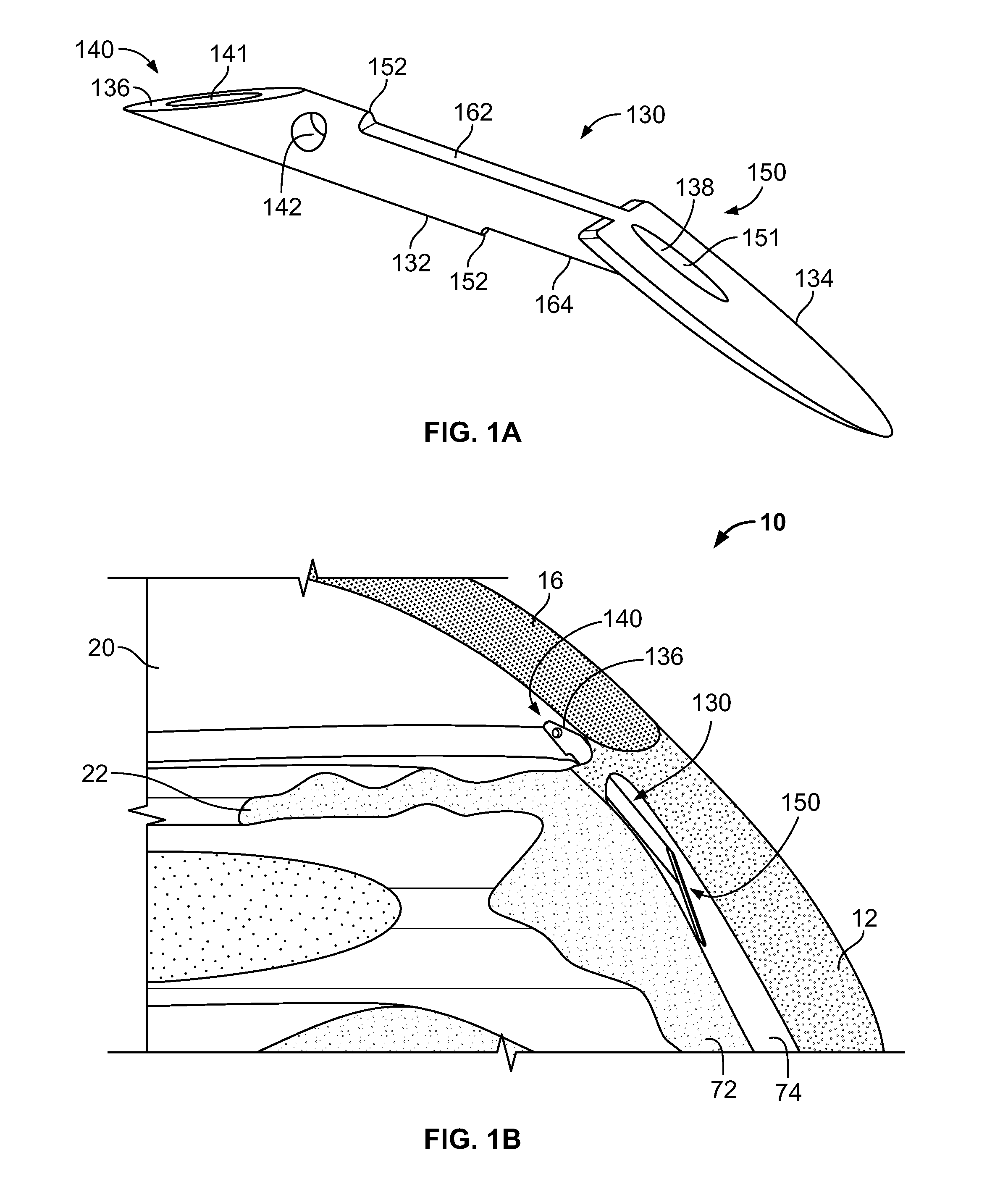
[0113]FIG. 1A shows a perspective view of an implant 130 in accordance with a first embodiment. The implant 130 in FIG. 1A is similar to implants described and illustrated in U.S. patent application Ser. No. 08 / 975,386, filed Nov. 20, 1997, now U.S. Pat. No. 6,203,513, the disclosure of which, as mentioned above, is incorporated by reference herein.

[0114]As can be seen in FIG. 1A, the implant 130 comprises a needle-like tube 132 and a disk or flange 134. The plane of the flange 134 forms an angle with the tube 132. The tube 132 has an inlet end 140, an outlet end 150, and a tube passage 138 extending between inlet end 140 and the outlet end 150, with the tube passage 138 having an axial inlet 141 and an axial outlet 151. The flange 134 is connected to the tube 132 at its outlet end 150.

[0115]The entire implant may be very small, and the size will depend on the intended application and implantation site. As one example, the tube 132 may have a length of about 2 mm to about 3 mm and a...


PUM

PropertyMeasurementUnit
thicknessaaaaaaaaaa
diameteraaaaaaaaaa
widthaaaaaaaaaa

Abstract

The disclosure provides an intraocular implant for allowing fluid flow from the anterior chamber of an eye, the implant comprising a tube having an inlet end, an outlet end, and a tube passage, wherein the inlet end is adapted to extend into the anterior chamber of the eye, and wherein the outlet end is adapted to be implanted adjacent scleral tissue of the eye. The implant may be adapted to drain aqueous humor into a suprachoroidal space or a juxta-uveal space. The disclosure also provides associated delivery devices, methods of use, and methods of manufacture.

Description

RELATED U.S. APPLICATIONS[0001]This application is a continuation-in-part of U.S. patent application Ser. No. 12 / 691,176, filed Jan. 21, 2010, which is a continuation of U.S. patent application Ser. No. 11 / 952,819, filed Dec. 7, 2007, now U.S. Pat. No. 7,670,310, which is a continuation of U.S. patent application Ser. No. 10 / 314,324, filed Dec. 9, 2002, now abandoned, which is a divisional of U.S. patent application Ser. No. 09 / 729,050, filed Dec. 4, 2000, now U.S. Pat. No. 6,510,600, which is a divisional of U.S. patent application Ser. No. 08 / 975,386, filed Nov. 20, 1997, now U.S. Pat. No. 6,203,513, the disclosures of which are hereby expressly incorporated herein by reference.FIELD OF THE INVENTION[0002]The invention relates to fluid drainage devices, such as for drainage of aqueous humor from the eye to treat glaucoma, and to delivery devices for implanting fluid drainage devices. The invention also relates to associated methods of use and manufacture.BACKGROUND OF THE INVENTIO...

Claims


Application Information

Patent Timeline
Patent Type & Authority Patents(United States)
IPC IPC(8): A61B19/00A61F11/00
CPCA61M27/002A61F9/00781Y10T83/0596
Inventor YARON, IRANISSAN, ODEDGOREN, GAL
Owner OPTONOL LTD
Why Eureka
Try Eureka