Network centric power flow control

a technology of power flow control and network centricity, applied in the field of electric power, can solve the problems of different amounts of the cost of producing electrical power may vary, and the power loss in the electrical power grid may be differen

Active Publication Date: 2012-11-20
THE BOEING CO
View PDF21 Cites 42 Cited by
  • Summary
  • Abstract
  • Description
  • Claims
  • Application Information

AI Technical Summary

Problems solved by technology

In an electrical power grid, this impedance in power lines leads to a loss of power in the electrical power grid.
These variations in demand may lead to different amounts of power loss in the electrical power grid, while delivering the same amount of power to a load.
Further, the cost of producing electrical power may vary for different electrical power sources and during the course of time.
However, increasing the voltage across power lines may require additional safety precautions.
In certain areas, increasing the voltage across power lines may be undesirable.
These electric providers may not have the resources and / or ability to manage the flow of electrical power in the electrical power grid in portions of the electrical power grids across these organizational boundaries.

Method used


Image

  • Network centric power flow control
  • Network centric power flow control
  • Network centric power flow control

Examples


Embodiment Construction

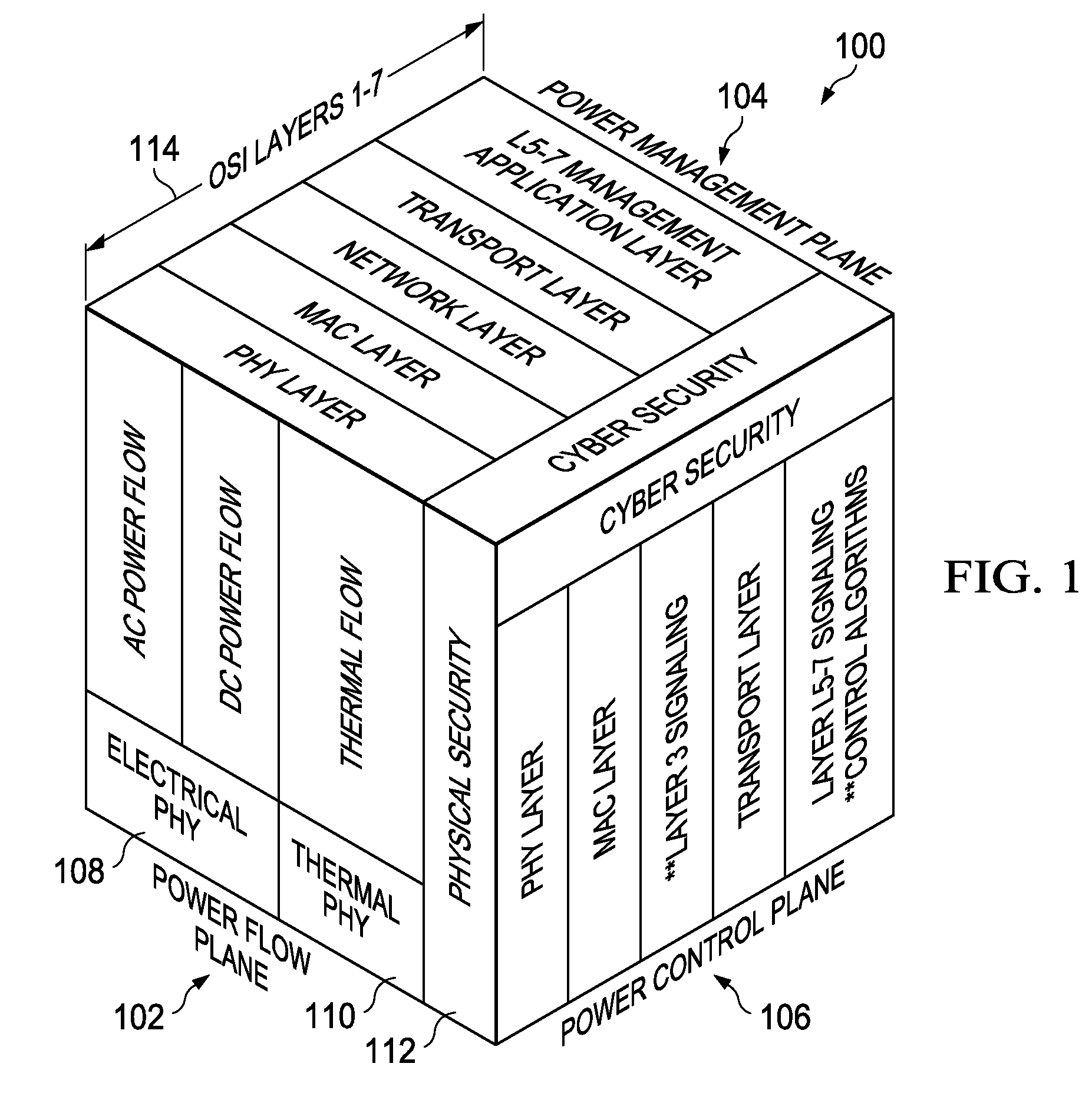
[0036]With reference now to FIG. 1, an illustration of a power model is depicted in accordance with an advantageous embodiment. In this illustrative example, power model 100 is a three-dimensional power model. Power model 100 may be used to model electrical power in an electrical power grid. More specifically, power model 100 allows power flow, power management, and power control for an electrical power grid to be treated independently of each other.

[0037]As depicted, power model 100 includes power flow plane 102, power management plane 104, and power control plane 106. In this illustrative example, power flow plane 102 includes physical aspects of the flow of electrical power through an electrical power grid. These physical aspects include electrical flow 108, thermal flow 110, and physical security 112.

[0038]In this illustrative example, power management plane 104 and power control plane 106 include layers 114, which are part of the Open System Interconnection (OSI) model. The Ope...


PUM


Abstract

A method and apparatus are present for sending power to a number of loads. A plurality of nodes and a number of lines connected to the plurality of nodes are selected to send electrical power from a number of sources to a number of loads based on a capacity to send the electrical power through the plurality of nodes and the number of lines. The plurality of nodes is configured into a circuit to carry the electrical power from the number of sources to the number of loads using the plurality nodes. The plurality of nodes are controlled to send the electrical power through the circuit to the number of loads using a number of agent processes associated with the plurality of nodes.

Description

CROSS-REFERENCE TO RELATED APPLICATION[0001]This application is related to patent application Ser. No. 12 / 709,407, entitled “Controlling Virtual Power Circuits”, filed even date hereof, and incorporated herein by reference.BACKGROUND INFORMATION[0002]1. Field[0003]The present disclosure relates generally to electrical power and, in particular, to electrical power flow. Still more particularly, the present disclosure relates to a method and apparatus for creating a circuit for transmitting and distributing electrical power.[0004]2. Background[0005]An electrical power source supplies electrical power to loads. The electrical power source may generate electrical energy from mechanical, chemical, thermal, and / or other types of energy. The electrical power source transmits this electrical energy as electrical power to the loads. A source may also store electrical energy that has been generated previously. Electrical power may be delivered from a number of sources to a number of loads usi...

Claims


Application Information

Patent Timeline
Patent Type & Authority Patents(United States)
IPC IPC(8): G05D3/12G05D17/00G05D11/00G05D9/00G05D5/00G06F15/16G05B11/01
CPCH02J3/14H02J13/002Y04S20/222Y02B70/3225H02J3/005H02J13/0006H02J13/00007H02J2310/12H02J13/00017H02J13/00004H02J13/00034
Inventor SACKMAN, RONALD WARDMEIER, JOHN LEOOVERMAN, THOMAS FRANCISMOODY, SCOTT ARTHUR
Owner THE BOEING CO
Why Eureka
Try Eureka