Method for producing plasma display panel
a plasma display and manufacturing method technology, applied in the manufacture of electrode systems, gas mixture absorption, instruments, etc., can solve the problems of increasing the electric power consumption, increasing the cost of a drive circuit, increasing the discharge voltage, etc., to reduce the damage to the prebaked substrate caused by rapid cooling, the effect of reducing the prebaked substrate and reducing the vapor pressur
- Summary
- Abstract
- Description
- Claims
- Application Information
AI Technical Summary
Benefits of technology
Problems solved by technology
Method used
Image
Examples
embodiment
Structure of PDP Apparatus
[0075]A PDP apparatus 1000 according to the embodiment includes a PDP 1 which is connected to predetermined drive circuits 111 to 113.
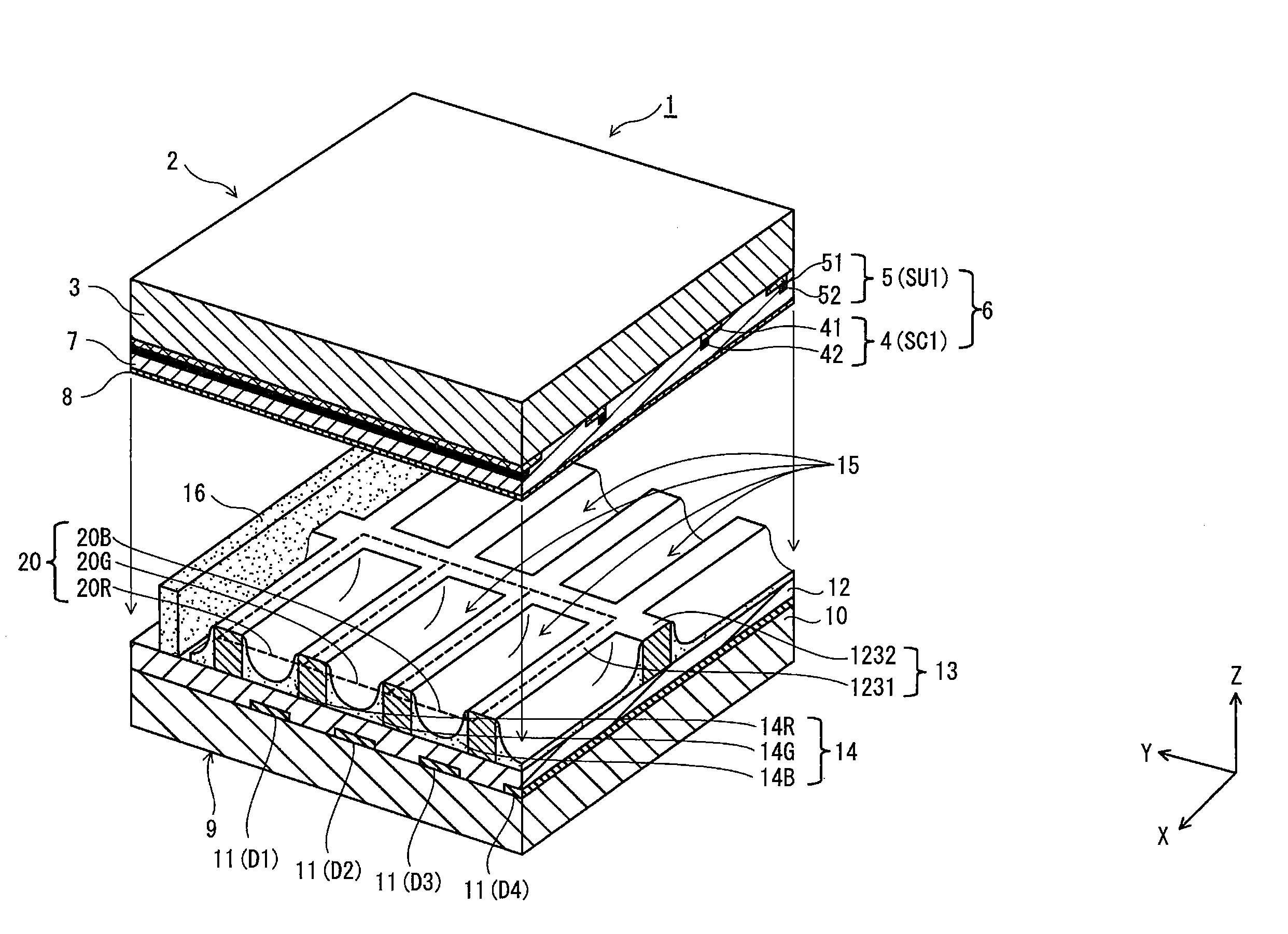
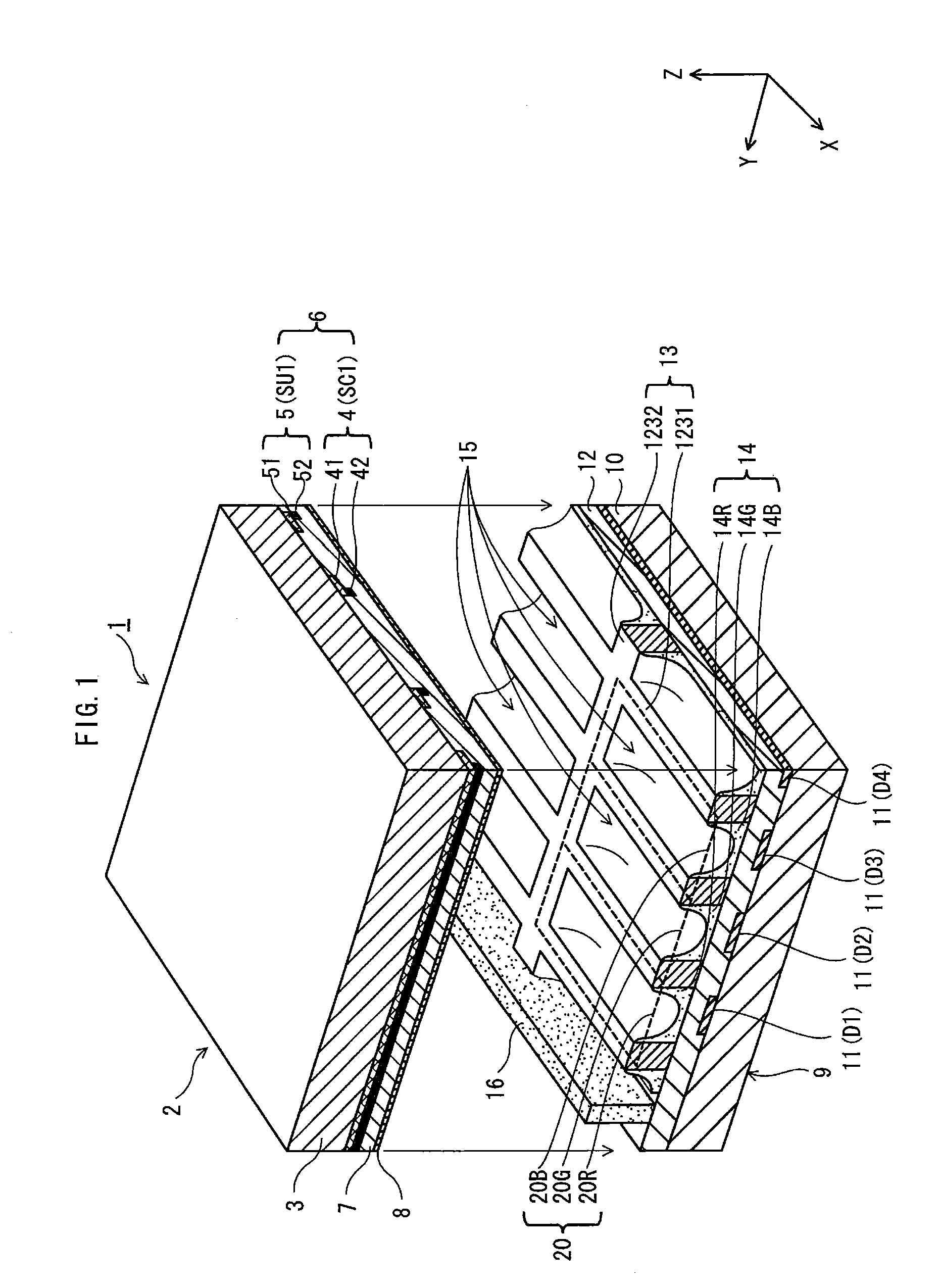
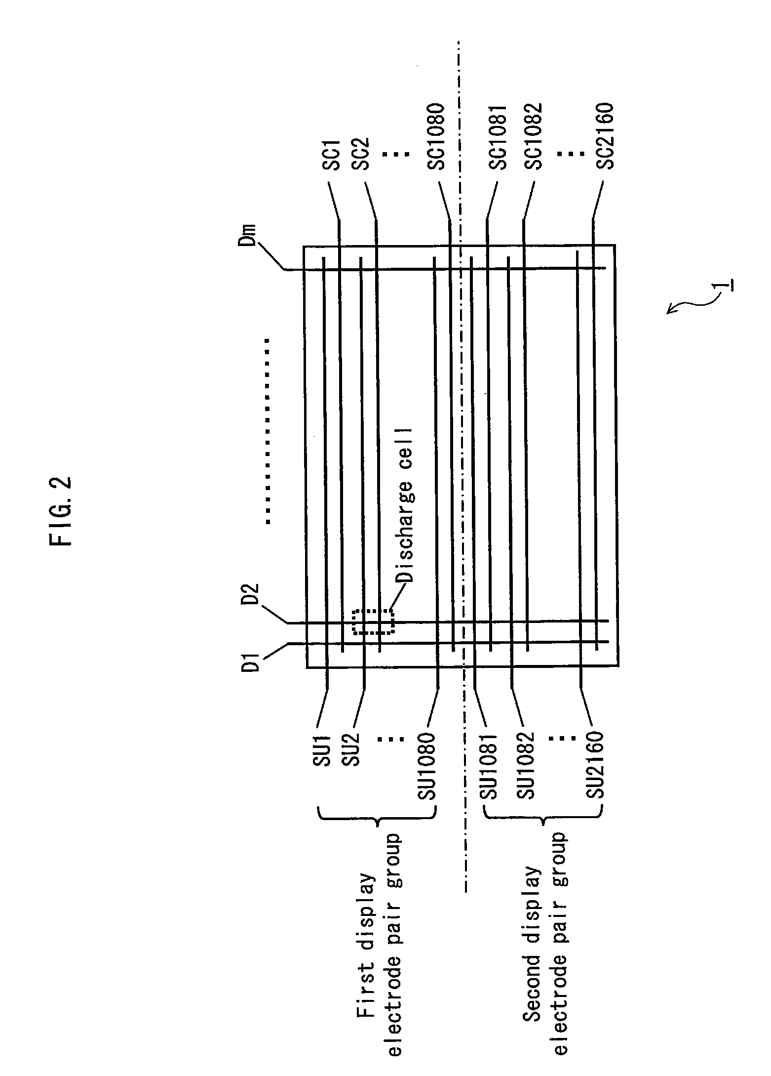
[0076]FIG. 1 is a perspective sectional view of an overall structure of the PDP 1, and partially shows an area in the vicinity of a sealing portion provided along peripheral edges of the PDP 1. FIG. 2 schematically shows an overall structure of electrode layout in the PDP 1.
[0077]As shown in FIG. 1, the PDP 1 is mainly composed of a front substrate (front panel) 2 and a back substrate (back panel) 9 that are sealed together along the peripheral edges thereof by a sealing portion 16 in a manner such that the panels 2 and 9 are superposed with a main inner surface of the front panel 2 opposing a main inner surface of the back panel 9.
[0078]The front substrate 2 includes a front substrate glass 3 as its basis. On the main surface of the front substrate glass 3, a plurality of display electrode pairs 6 (each composed of a scan el...
example 1
[0300]A PDP including small cells with a cell pitch of approximately 0.10 mm was manufactured. In the front substrate manufacturing process, the protective layer containing only MgO was obtained by distributing O2 at 0.1 (sccm) in the EB apparatus using the MgO pellet.
[0301]As the phosphors, (Y, Gd) BO3:Eu was used as red phosphors, Zn2SiO4:Mn was used as green phosphors, and BaMgAl10O17:Eu was used as blue phosphors.
[0302]As a composition of the sealing material, PbO—B2O3—RO-MO-based glass composed mainly of lead oxide-based (PbO) glass as shown in later-described Table 1 was used. The softening point of the above sealing material is 430° C., and the flow point of the sealing material is 490° C.
[0303]The highest pre-baking temperature (in the step 2 in the temperature profile of FIG. 12) in the pre-baking step was set to be 400° C. which was 30° C. lower than the softening point of the sealing material. The pre-baking step was performed for 50 minutes in the atmosphere.
[0304]In the...
example 2
[0309]The sealing step was performed in the mixed gas atmosphere consisting of the N2 gas mixed with the H2 gas, with the partial pressure of the H2 gas being 3.0%, as shown in Table 1. Apart from that, settings in Example 2 are basically the same as Example 1.
PUM
 Abstract
Description
Claims
Application Information
 - R&D
- Intellectual Property
- Life Sciences
- Materials
- Tech Scout
- Unparalleled Data Quality
- Higher Quality Content
- 60% Fewer Hallucinations
Browse by: Latest US Patents, China's latest patents, Technical Efficacy Thesaurus, Application Domain, Technology Topic, Popular Technical Reports.
© 2025 PatSnap. All rights reserved.Legal|Privacy policy|Modern Slavery Act Transparency Statement|Sitemap|About US| Contact US: help@patsnap.com


