
Removable blood clot filter with edge for cutting through the endothelium

a filter and endothelium technology, applied in the field of filter devices, can solve the problems of aversion to receiving a permanent implant, potential rupture, and risk of injury to the vena cava, and achieve the effects of reducing the risk of vascular damag

Active Publication Date: 2012-11-27
CR BARD INC
View PDF50 Cites 12 Cited by
  • Summary
  • Abstract
  • Description
  • Claims
  • Application Information

AI Technical Summary

Benefits of technology

"The patent describes a removable blood filter that can be easily removed without harming the blood vessel walls. The filter includes a hub and several anchor members and locator members. The anchor members have a hook that penetrates the blood vessel wall and a sharp edge, while the locator members have a base portion, first and second portions, and a tip portion that engages the blood vessel wall. The method of making the filter involves adding or removing material to create the sharp edge. The technical effect of this invention is a blood filter that can be easily and safely removed without causing any damage to the blood vessel."

Problems solved by technology

Thereafter, any attempt to remove the filter results in a risk of injury to the vena cava, including potential rupture.
In such cases, patients are often averse to receiving a permanent implant because the risk of pulmonary embolism may disappear after a period of several weeks or months.
However, not all existing filters are conducive to removal after they have been implanted for more than two weeks.
Moreover, most existing filters have different consequences on the vessel wall during removal subsequent to the two-week time period.
For example, a known filter is believed to cause the vessel wall diameter to collapse substantially upon removal of such filter due to the attachment of the hooks to the vessel wall.
But after the endothelium layer grows over the locators, the combined inward and longitudinal movement of the filter baskets as they are drawn apart can tear this layer.
Nevertheless, if the filter has been in the blood vessel for several weeks, the endothelial overgrowth may be substantial enough to be vulnerable to lateral movement of the anchor and hook.
If the endothelial overgrowth 7 does not easily tear or split, the overgrowth may complicate removal of the filter or the blood vessel may be damaged.

Method used


Image

  • Removable blood clot filter with edge for cutting through the endothelium
  • Removable blood clot filter with edge for cutting through the endothelium
  • Removable blood clot filter with edge for cutting through the endothelium

Examples


Embodiment Construction

[0037]The various embodiments will be described in detail with reference to the accompanying drawings. Wherever possible, the same reference numbers will be used throughout the drawings to refer to the same or like parts.

[0038]As used herein, the terms “about” or “approximately” for any numerical values or ranges indicates a suitable dimensional tolerance that allows the part or collection of components to function for its intended purpose as described herein. Also, as used herein, the terms “patient,”“host” and “subject” refer to any human or animal subject and are not intended to limit the systems or methods to human use, although use of the subject invention in a human patient represents a preferred embodiment.

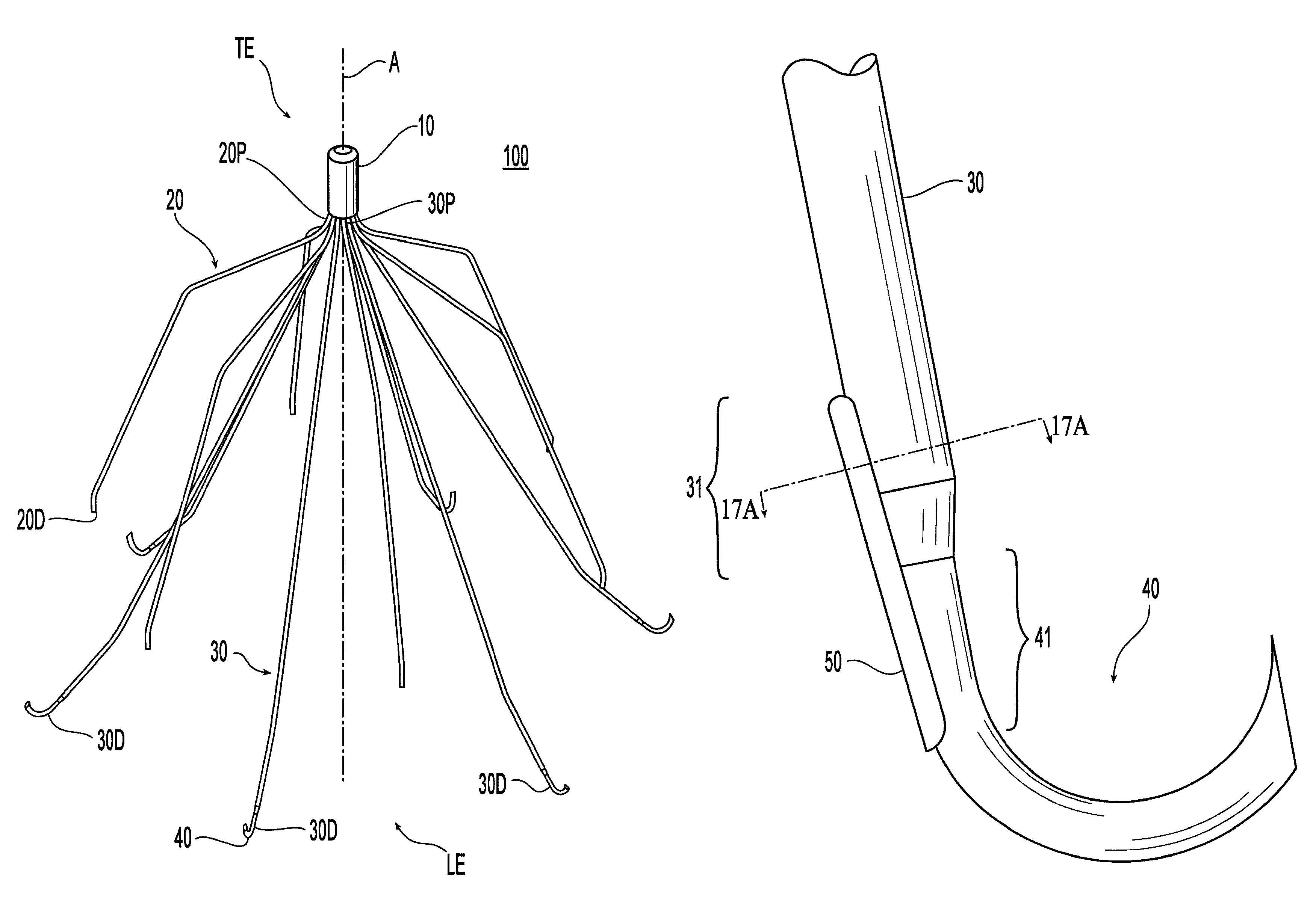
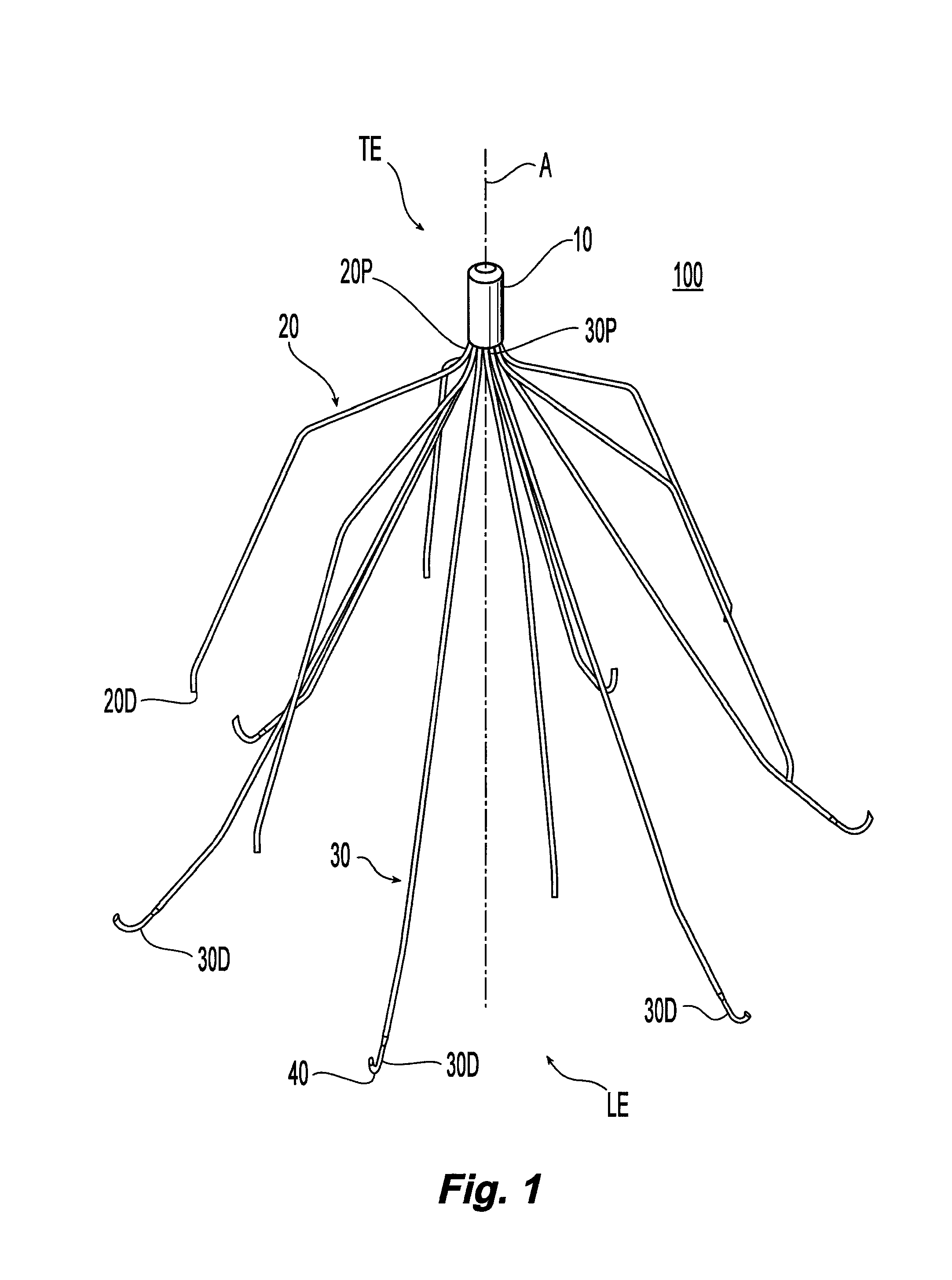
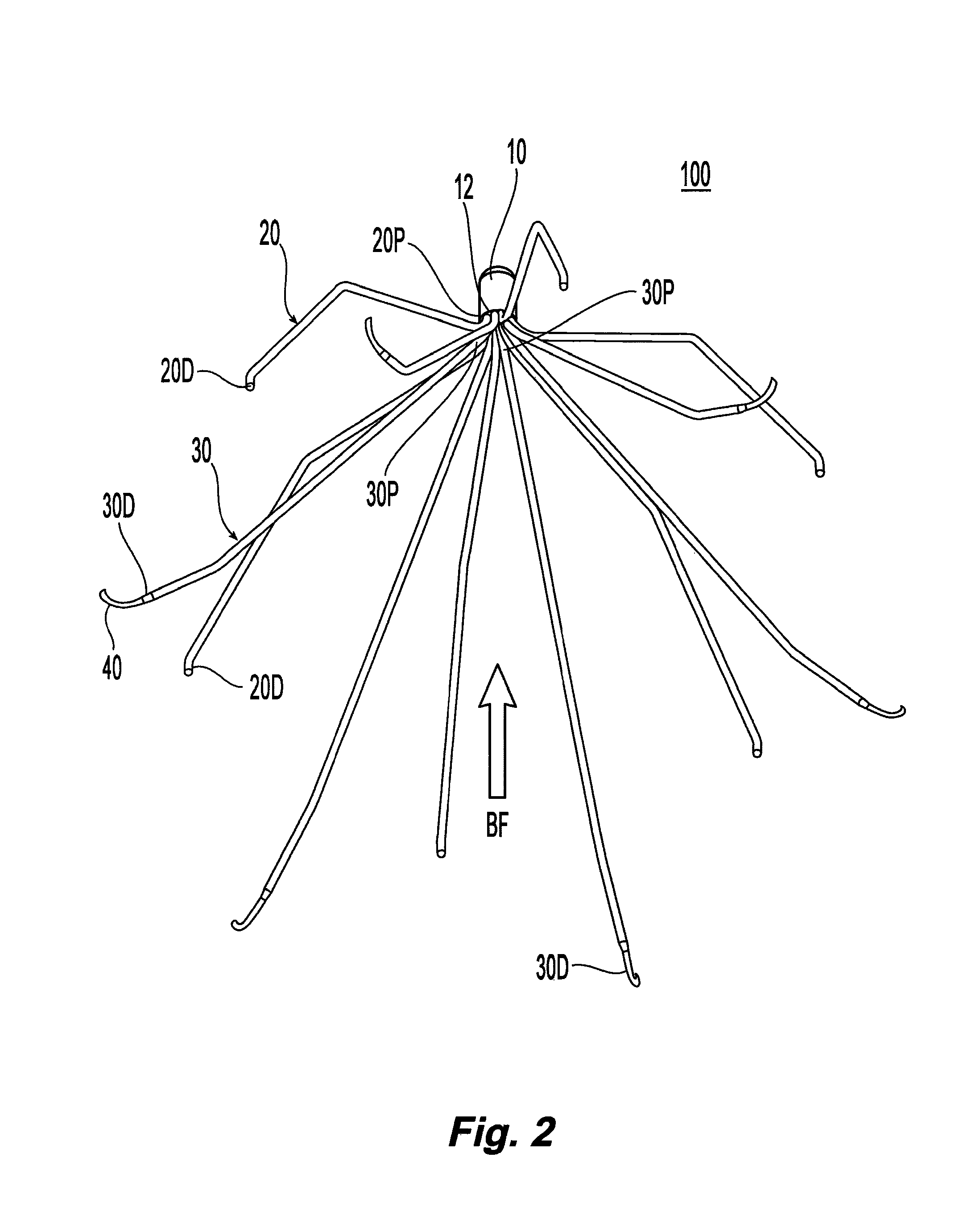
[0039]Referring to FIG. 1, a filter 100 is illustrated in a perspective view. The filter 100 includes a hub 10, locator members 20, and anchor members 30 with hooks 40. The filter 100 can be made from a plurality of elongate wires, which are preferably metal such as Elgiloy...


PUM

PropertyMeasurementUnit
lengthaaaaaaaaaa
lengthaaaaaaaaaa
lengthaaaaaaaaaa

Abstract

A removable blood clot filter includes anchor members with a sharp edge configured so that when the filter is removed the sharp edge aids in passing the anchor members through endothelial tissue. The filter may also include a sharp edge on locator members configured to aid pulling the locator members away from the endothelial tissue.

Description

PRIORITY DATA AND INCORPORATION BY REFERENCE[0001]This application claims benefit of priority to U.S. Provisional Patent Application No. 60 / 754,600, filed Dec. 30, 2005 which is incorporated by reference in its entirety. This invention is related to the subject matter shown and described in the following: (i) PCT International Application No. PCT / US06 / 62733, filed Dec. 29, 2006, entitled “Embolus Blood Clot Filter Removal System and Method,” and claiming the benefit of priority to U.S. Provisional Patent Application No. 60 / 754,598, filed Dec. 30, 2005; (ii) PCT International Application No. PCT / US06 / 62719, filed Dec. 29, 2006, entitled “Embolus Blood Clot Filter with Post Delivery Actuation,” and claiming the benefit of priority to U.S. Provisional Patent Application No. 60 / 754,633, filed Dec. 30, 2005; (iii) PCT International Application No. PCT / US06 / 62725, filed Dec. 29, 2006, entitled “Embolus Blood Clot Filter Delivery System,” and claiming the benefit of priority to U.S. Provis...

Claims


Application Information

Patent Timeline
Patent Type & Authority Patents(United States)
IPC IPC(8): A61F2/01
CPCA61F2/01A61F2002/016Y10T29/49826A61F2230/0067A61F2230/008A61F2230/005A61F2/0105
Inventor KASHKAROV, ALEXANDER GERMANOVICHCHANDUSZKO, ANDRZEJ J.
Owner CR BARD INC
Learn More