Injection device and ampoule unit
- Summary
- Abstract
- Description
- Claims
- Application Information
AI Technical Summary
Benefits of technology
Problems solved by technology
Method used
Image
Examples
Embodiment Construction
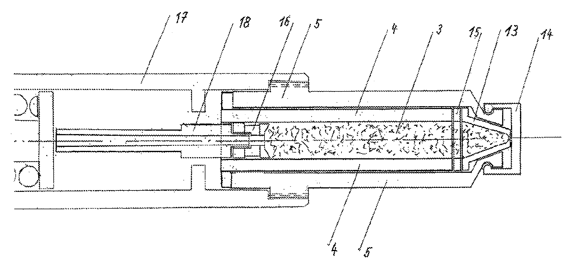
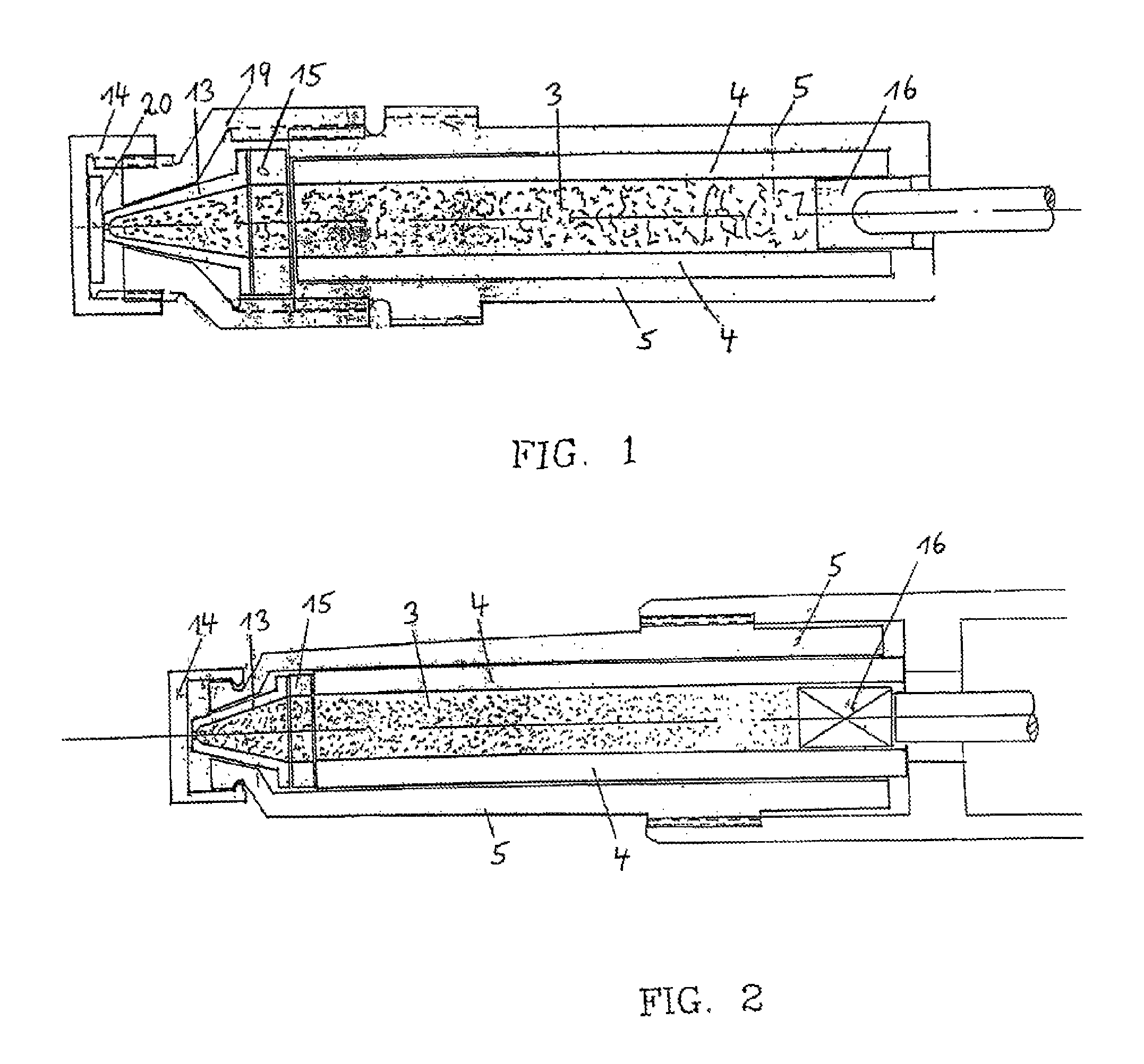
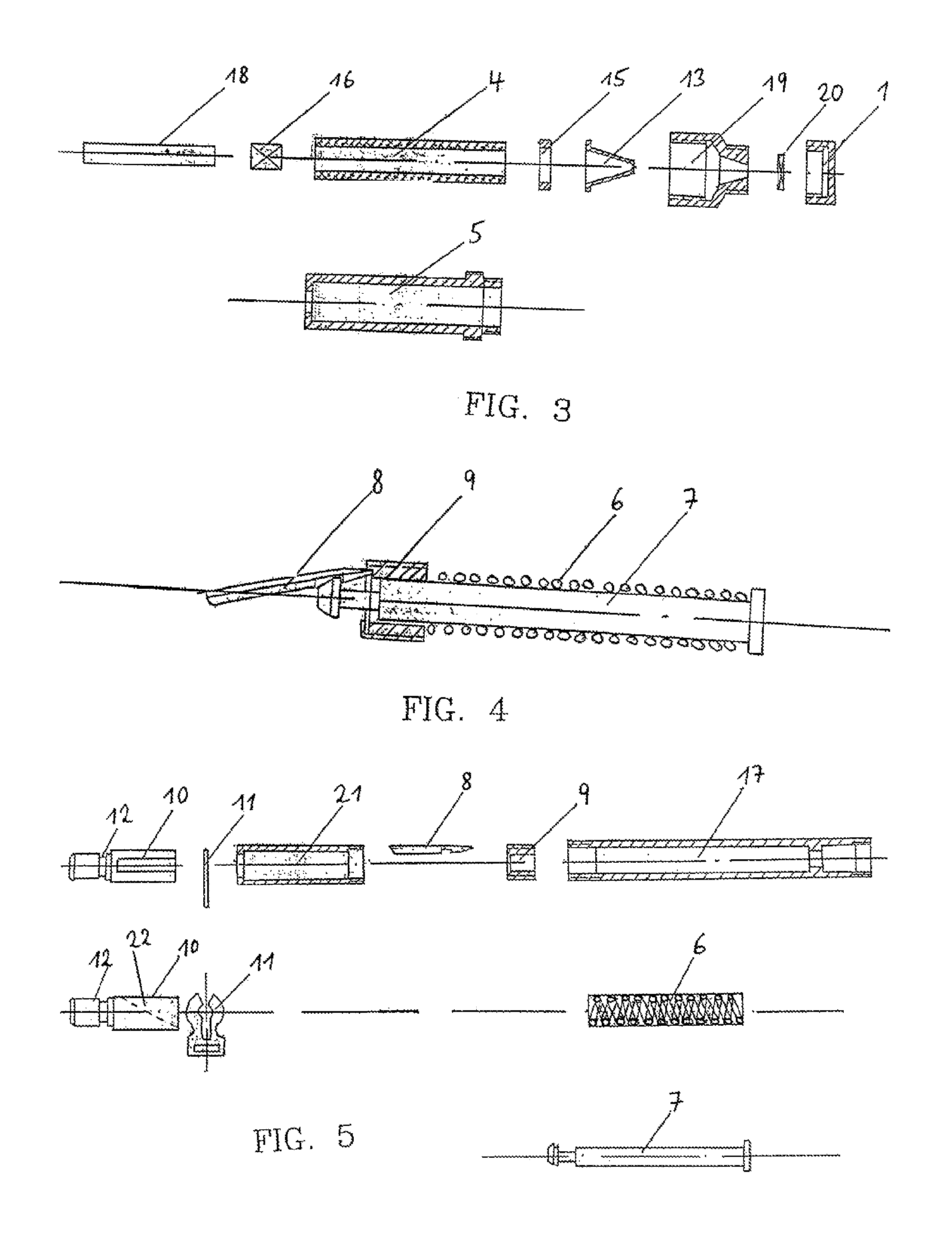
[0046]FIG. 1 shows a schematic representation of cross-sectional view of an ampoule unit 2 which has a stopper element 16 (with a plunger rod as tentatively indicated) on one of its axially longitudinal ends. On the other axially longitudinal end of the jacketed 5 base body 4 which is filled with a medium 3 and which, in the direction of the longitudinal axis, is completely enveloped by the jacket 5. A sealing element 15 made of silicone is disposed between the steel nozzle 13 and the base body 4 and jacket 5. The steel nozzle 13 is mechanically attached so as to seal off the medium in a friction-locked and form-fitting manner by a nozzle screw joint 19. At the discharge end of the steel nozzle 13, a cap 14 is screwed on, with a cap seal 20 being disposed (for reasons of sterility) between the inside wall of the cap 14 and the discharge end of the steel nozzle 13. Prior to the injection, the ampoule unit 2 is attached to, in particular screwed onto, an injector device 1 so that, aft...
PUM
 Abstract
Description
Claims
Application Information
 - R&D
- Intellectual Property
- Life Sciences
- Materials
- Tech Scout
- Unparalleled Data Quality
- Higher Quality Content
- 60% Fewer Hallucinations
Browse by: Latest US Patents, China's latest patents, Technical Efficacy Thesaurus, Application Domain, Technology Topic, Popular Technical Reports.
© 2025 PatSnap. All rights reserved.Legal|Privacy policy|Modern Slavery Act Transparency Statement|Sitemap|About US| Contact US: help@patsnap.com


