Reactor comprising a stack of filter plates

a filter plate and reactor technology, applied in the direction of multi-stage water/sewage treatment, membranes, separation processes, etc., can solve the problem of inadequate and achieve the effect of encouraging fluid circulation within the reactor

Active Publication Date: 2012-11-27
GRUNDFOS MANAGEMENT AS
View PDF28 Cites 0 Cited by
  • Summary
  • Abstract
  • Description
  • Claims
  • Application Information

AI Technical Summary

Benefits of technology

[0005]It is the object of the present invention to improve the fluid circulation in a reactor, as much as possible, without the application of additional pump power.
[0009]According to a further formation of the invention, the filter plate stack is advantageously attached in the end region of the reactor housing, wherein the drive for the rotation of the filter plate stack is usefully led through the end-side of the reactor housing and is arranged outside the housing. The arrangement of the drive outside the housing is particularly favorable, since it is not to be encapsulated with respect to the surroundings, is easily accessible and is inexpensive to attach. Moreover, in particular, the lead-through and attachment on the end-side of the reactor housing makes particular sense, since, then, the typically cylindrical housing does not need to undergo any special mechanical machining.
[0012]According to a further formation of the invention, the drive for the biofilm reactor may be effected via the drive of the filter unit, advantageously by way of a mechanical coupling between the filter plate stack and the rotatable part of the biofilm reactor. One may completely make do without a separate drive for the biofilm reactor by way of this, i.e., a mechanical drive is only to be provided on one side of the reactor, which is simple and inexpensive with regard to design, and which furthermore creates free space at the other end, for the attachment of other assemblies.
[0014]The flow through the reactor housing may be yet encouraged by way of it being arranged in an inclined manner. Thereby, a slight oblique position in a manner such that the longitudinal axis of the reactor housing encloses an angle of preferably below 30° with the horizontal, has been found to be advantageous. Such an oblique position effects a targeted gas discharge to the upper, obliquely set end within the reactor, as well as a circulation which is caused by gravitation and which may support the pump effect of the filter plate stack. Thereby, a gas bubble in the upper region of the reactor is advantageous already for hydraulic reasons, since pressure peaks may be absorbed and damped by way of this, which otherwise could only be absorbed in a secure manner of complicated valve technology given a reactor which is completely filled with fluid.
[0017]Moreover, a ventilation device may be provided in a targeted manner for the reactor, with which for example a gas flow or air flow is applied at a predefined location, which in particular with an oblique arrangement of the container, flows through this and remains in the upper region of the reactor or is led away there again. The ventilation device may, depending on the demands, be designed as a closed, partly open or open system. The gas supply may be effected through the filter plate stack itself, usefully through separate gas feed channels within the central channel which is provided for the filtrate discharge. Thereby, the discharge of the ventilation device is usefully effected through the filter plate stack itself, preferably through the filter surface, in the reverse throughflow direction to the fluid. A high surface effect is achieved with the flow of the gas through the filter fluid, and the gas feed, in particular the air feed, is finely distributed, i.e., is introduced into the reactor with a large surface, which intensifies its effectiveness. If the filter plate stack is not to be affected by the ventilation device with regard to its functioning, it is then useful to arrange the discharge of the ventilation device within the region of the reactor housing, which is distant to the filter plate stack.
[0019]In order to encourage the circulation within the reactor, it is advantageous to arrange a suction tube at the end of the filter plate stack, through which suction tube the fluid to be filtered is sucked within the reactor housing. Thereby, it has been shown to be advantageous not to arrange the suction opening directly on the filter plate stack, but at a distance to the filter plate stack, which corresponds at least to double the height of the filter plate stack.

Problems solved by technology

However, here, the fluid circulation within the reactor is inadequate if one does not deliver it through the reactor with a sufficiently high pump power.

Method used


Image

  • Reactor comprising a stack of filter plates
  • Reactor comprising a stack of filter plates
  • Reactor comprising a stack of filter plates

Examples


Embodiment Construction

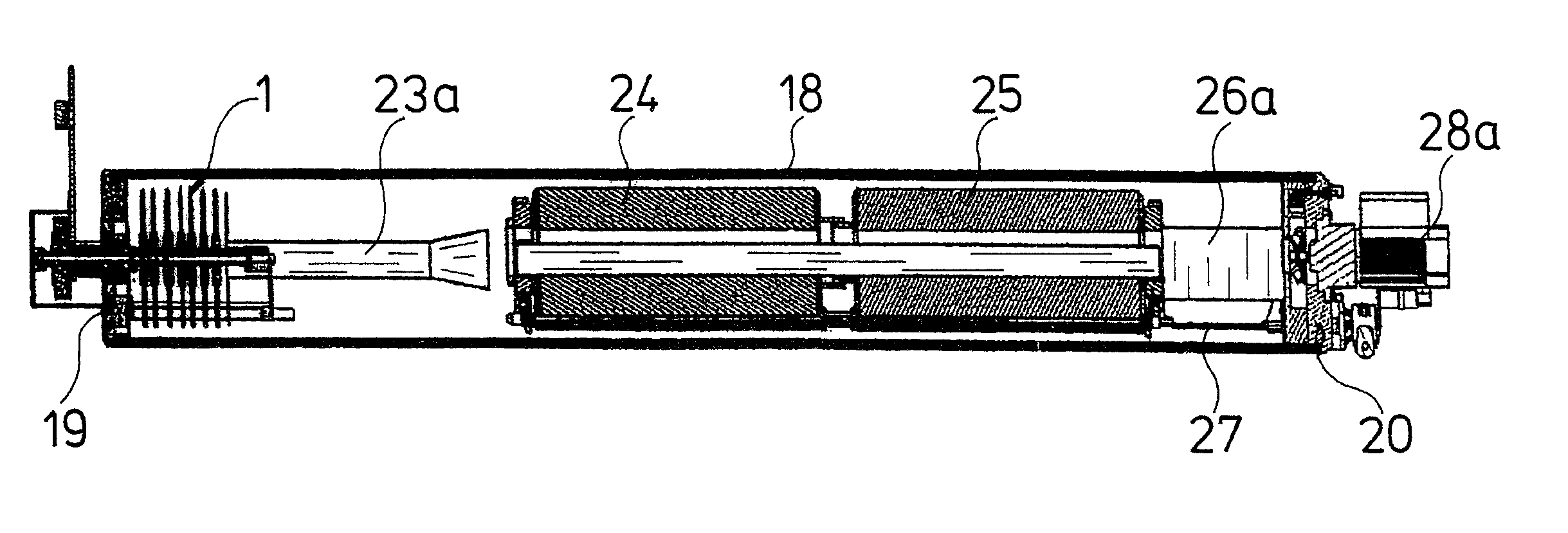
[0038]The reactors represented by way of example in the FIGS. 8 to 15 in each case comprise a filter plate stack 1 which is formed of a multitude of filter plates which are arranged concentrically to one another and are placed onto one another into a stack, whose construction is to be deduced in detail from the FIGS. 1 to 4.

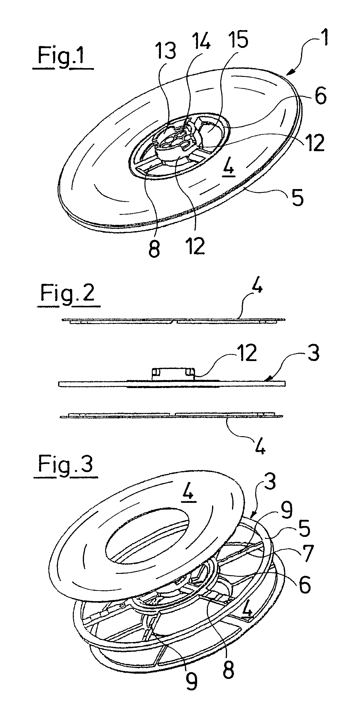
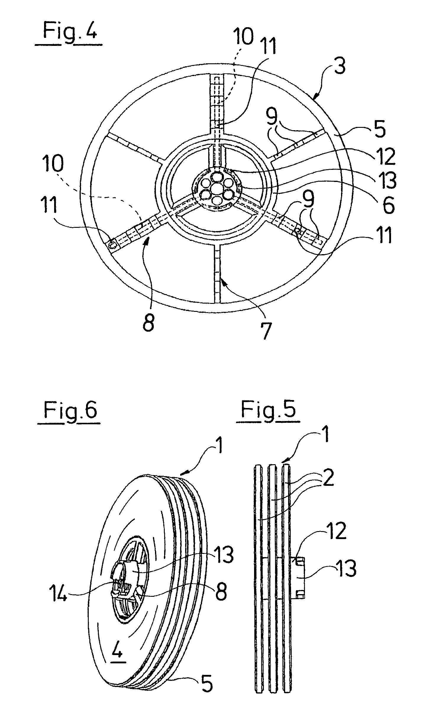
[0039]Each filter plate 2 comprises a central component 3, which for example may be designed as an injection moulded part of plastic, and which represents the carrying and channel-forming function of the filter plate 2. The actual filter is formed by two annular filter disks 4 which are arranged on the central component 3 on both sides, and together with this, form the filter plate 2. The central component 3 has a circular shape in a plan view (FIG. 4) and comprises a closed outer ring 5 on its outer periphery, whose outer side also forms the outer side of the filter plate 2. An inner ring 6 is arranged at a radial distance within the outer ring 5 and is connecte...


PUM

PropertyMeasurementUnit
speedaaaaaaaaaa
diameteraaaaaaaaaa
angleaaaaaaaaaa

Abstract

A reactor includes a tubular-shaped housing in which a stack of filter plates can be rotationally arranged. The cross-sectional area of the reactor container is, in the region of the stack of filter plates, a maximum of 40% greater than the cross-sectional area of the stack of filter plates. The longitudinal extension of the reactor housing is a multiple of the longitudinal extension of the stack of filter plates, such that inside the reactor, adjacent to the stack of filter plates, additional processing devices can be arranged. The rotating stack of filter plates ensures that the entire reactor is cross-flown in an intensive manner.

Description

CROSS-REFERENCE TO RELATED APPLICATIONS[0001]This application is a Section 371 of International Application No. PCT / EP2007 / 003847, filed May 2, 2007, which was published in the German language on Nov. 15, 2007, under International Publication No. WO 2007 / 1218467 A1 and the disclosure of which is incorporated herein by reference.BACKGROUND OF THE INVENTION[0002]The invention relates to a reactor for treating fluids, in particular for water treatment.[0003]The treatment of waste water may be effected mechanically, e.g., by way of filters, biologically, chemically, or physically as well as with a combination of these mentioned methods. With biological fluid treatment, it is counted as belonging to the state of the art to apply so-called reactors in which the fluid to be treated is led to a large, biologically active surface. Such a reactor is known, for example, from International Publication No. WO 02 / 094721 A1. The reactor described there comprises two plate stacks which mesh with on...

Claims


Application Information

Patent Timeline
Patent Type & Authority Patents(United States)
IPC IPC(8): B01D33/00
CPCB01D33/21B01D61/18B01D63/16B01J8/006C02F1/004C02F3/101C02F3/2806B01D35/26Y02W10/15B01D2313/08B01D2313/16B01D2313/24B01D2315/02C02F1/008C02F3/08C02F9/00C02F2001/46123C02F2209/42C02F1/001Y02W10/10
Inventor BELDRING, FINNRASMUSSEN, CHRISTIAN
Owner GRUNDFOS MANAGEMENT AS
Why Eureka
Try Eureka