
Liquid crystal display panel and method of manufacturing the liquid crystal display panel

a technology of liquid crystal display panel and liquid crystal display panel, which is applied in the direction of thin material processing, instruments, chemistry apparatus and processes, etc., can solve the problems of reducing display quality, increasing power consumption, and inducing non-uniform pretilt of liquid crystal molecules, so as to improve the curing rate or the polymerization rate of reactive mesogens, improve the curing rate or the polymerization rate of free radicals, and improve the effect of structur

Inactive Publication Date: 2012-11-27
SAMSUNG DISPLAY CO LTD
View PDF2 Cites 10 Cited by
  • Summary
  • Abstract
  • Description
  • Claims
  • Application Information

AI Technical Summary

Benefits of technology

The patent text describes a liquid crystal display panel with improved reliability and a method of manufacturing it. The panel includes a first substrate with a pixel electrode and a first alignment layer, a second substrate with a common electrode layer and a second alignment layer, and a liquid crystal layer between the two substrates. The liquid crystal layer includes a first liquid crystal compound, a second liquid crystal compound, and a third liquid crystal compound. The first liquid crystal compound has a structure that absorbs light energy effectively. The method of manufacturing the panel involves disposing the substrates and injecting liquid crystal molecules between them, followed by polymerizing a reactive mesogen to form the first and second reactive mesogen layers on the substrates. The technical effects of this patent include improved reliability of the LCD panel and reduced manufacturing time.

Problems solved by technology

When the photoactive monomer remains within the liquid crystal layer, the photoactive monomer may be cured by the backlight in a specific area during driving of the LCD panel, thereby inducing a non-uniform pretilt of the liquid crystal molecules.
The non-uniform pretilt may display as an afterimage on the LCD panel and become one factor in a reduced display quality.
However, the increasing of the illumination intensity of the light source to increase the energy for the curing may result in increased power consumption and increased manufacturing cost.
In addition, the liquid crystal molecules and / or an alignment layer may be damaged, deteriorating the display quality.
Further, when the exposure time is increased, the processing time for manufacturing the LCD panel increases, further reducing productivity.

Method used


Image

  • Liquid crystal display panel and method of manufacturing the liquid crystal display panel
  • Liquid crystal display panel and method of manufacturing the liquid crystal display panel
  • Liquid crystal display panel and method of manufacturing the liquid crystal display panel

Examples


Embodiment Construction

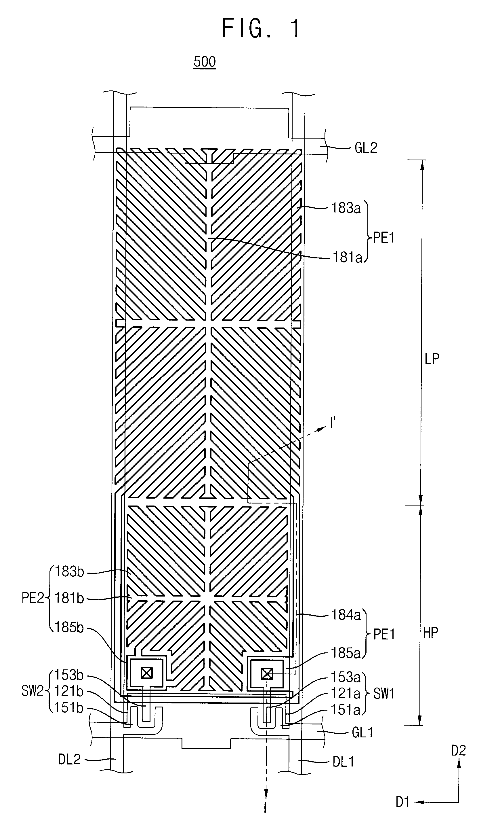
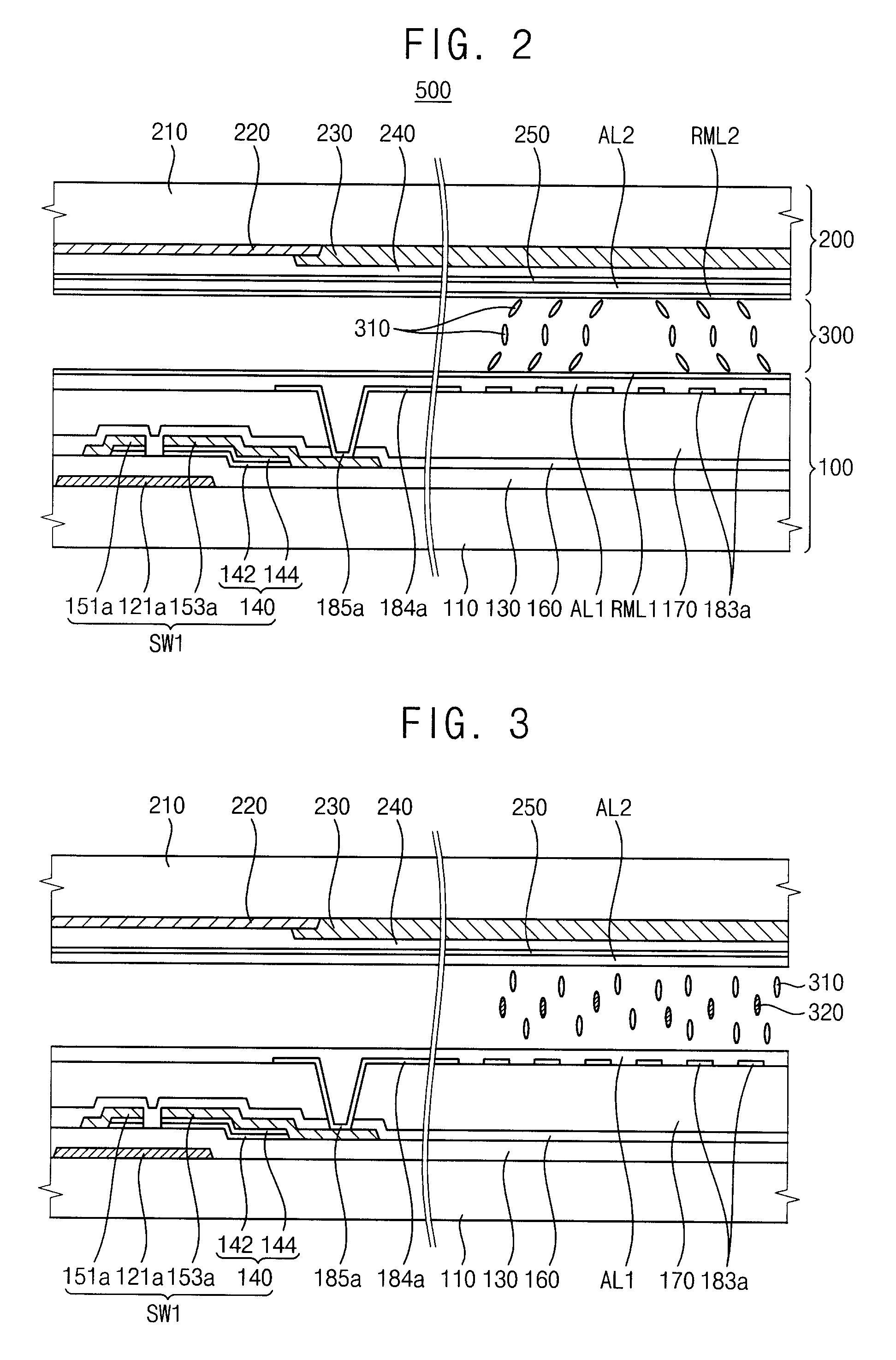
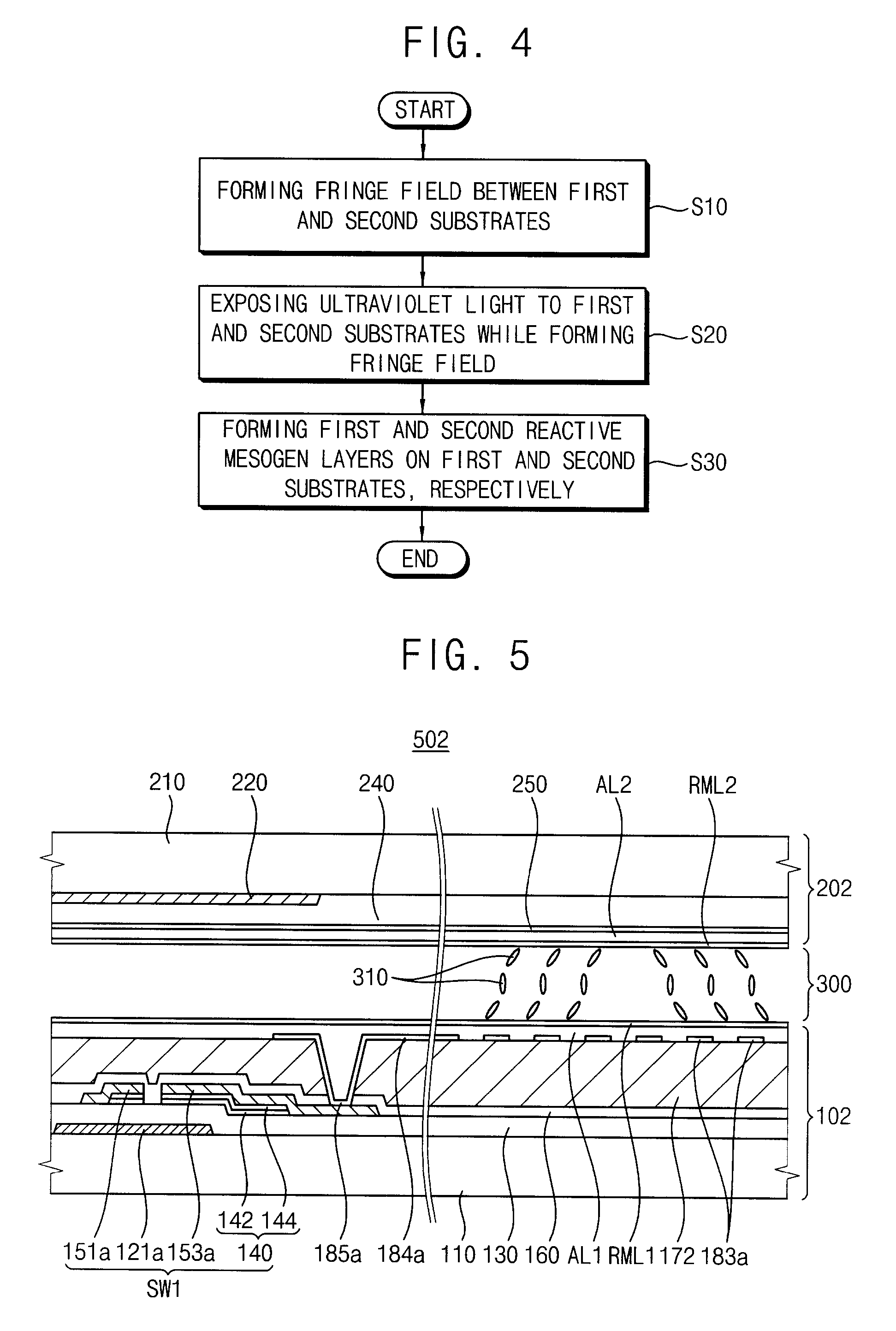
[0030]The present invention is described more fully hereinafter with reference to the accompanying drawings, in which exemplary embodiments of the present invention are shown. The present invention may, however, be embodied in many different forms and should not be construed as limited to the exemplary embodiments set forth herein. Rather, these exemplary embodiments are provided so that this disclosure will be thorough and complete, and will fully convey the scope of the present invention to those skilled in the art. In the drawings, the sizes and relative sizes of layers and regions may be exaggerated for clarity.

[0031]It will be understood that when an element or layer is referred to as being “on,”“connected to” or “coupled to” another element or layer, it can be directly on, connected or coupled to the other element or layer or intervening elements or layers may be present. In contrast, when an element is referred to as being “directly on,”“directly connected to” or “directly co...


PUM

PropertyMeasurementUnit
rotational viscosityaaaaaaaaaa

Abstract

A liquid crystal display (“LCD”) panel includes a first substrate including a pixel electrode defining pixel areas, a first alignment layer disposed on the pixel electrode and a first reactive mesogen layer disposed on the first alignment layer, a second substrate including a common electrode layer disposed on an entire portion of the second substrate facing the first substrate, a second alignment layer disposed on the common electrode layer and a second reactive mesogen layer disposed on the second alignment layer, and a liquid crystal layer disposed between the first and second substrates and including a first liquid crystal compound represented by Chemical Formula 1, a second liquid crystal compound represented by Chemical Formula 2 and a third liquid crystal compound represented by Chemical Formula 3:

Description

[0001]This application claims priority to Korean Patent Application No. 2009-0021522, filed on Mar. 13, 2009, and all the benefits accruing therefrom under 35 U.S.C. §119, the content of which in its entirety is herein incorporated by reference.BACKGROUND OF THE INVENTION[0002]1. Field of the Invention[0003]Exemplary embodiments relate to a liquid crystal display (“LCD”) panel and a method of manufacturing the LCD panel. In particular, exemplary embodiments relate to an LCD panel including a liquid crystal composition and a method of manufacturing the LCD panel.[0004]2. Description of the Related Art[0005]Generally, an image is displayed on an LCD panel according to light transmittance of a liquid crystal layer, which is electrically controlled. An LCD panel having a patterned vertical alignment (“PVA”) mode, which is a type of LCD panel having a vertical alignment (“VA”) mode, has been developed to improve a viewing angle by aligning liquid crystal molecules in different directions...

Claims


Application Information

Patent Timeline
Patent Type & Authority Patents(United States)
IPC IPC(8): C09K19/00C09K19/52C09K19/06G02F1/1337C09K19/30
CPCC09K19/12C09K19/44G02F1/133711C09K2019/0407C09K2019/0411C09K2019/0448C09K2019/123Y10T428/1005G02F2001/133726G02F2001/133742G02F2001/133761Y10T428/1036Y10T428/10C09K2019/3025C09K2323/00C09K2323/02C09K2323/03G02F1/133726G02F1/133742G02F1/133761C09K19/56G02F1/1337
Inventor SEONG, DONG-GILYU, JAE-JINPARK, SEUNG-BEOMKYE, MYEONG-HASEOK, MIN-GOOKIM, MIN-HEE
Owner SAMSUNG DISPLAY CO LTD
Learn More