
System and method for imaging objects

a technology of imaging system and object, applied in the field of detection and imaging system, can solve the problems of inability to determine whether the detected metal object is a threat object (e.g., knife or gun) or an innocent object (non-threat), detection system cannot pinpoint the location of the metal object on the individual's body, and system is useless in the detection of modern threats posed by plastic and ceramic items and plastic and liquid explosives. to achieve the effect of eliminating the disadvantages of conventional imaging

Active Publication Date: 2012-11-27
ELTA SYST LTD
View PDF47 Cites 24 Cited by
  • Summary
  • Abstract
  • Description
  • Claims
  • Application Information

AI Technical Summary

Benefits of technology

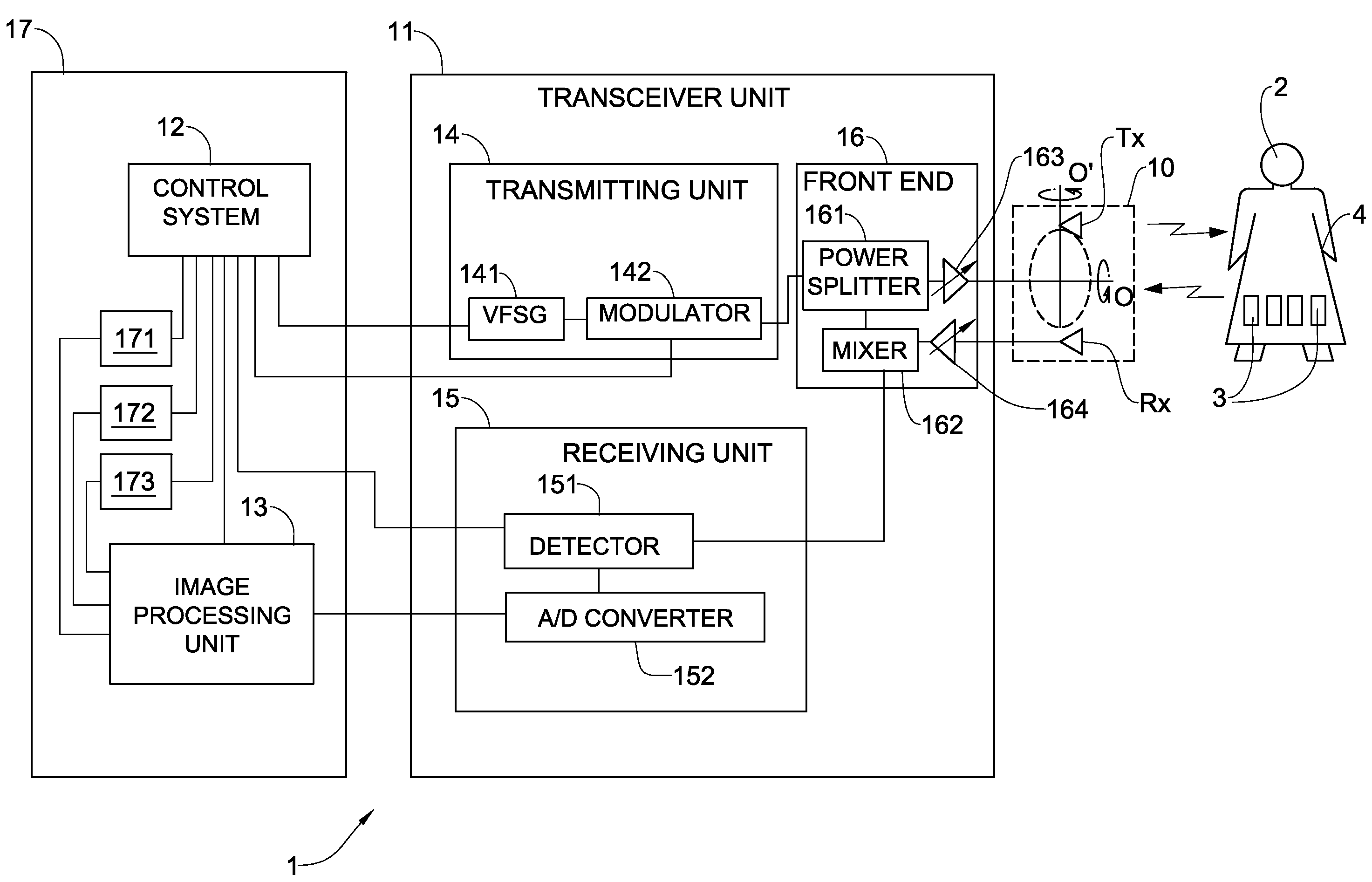
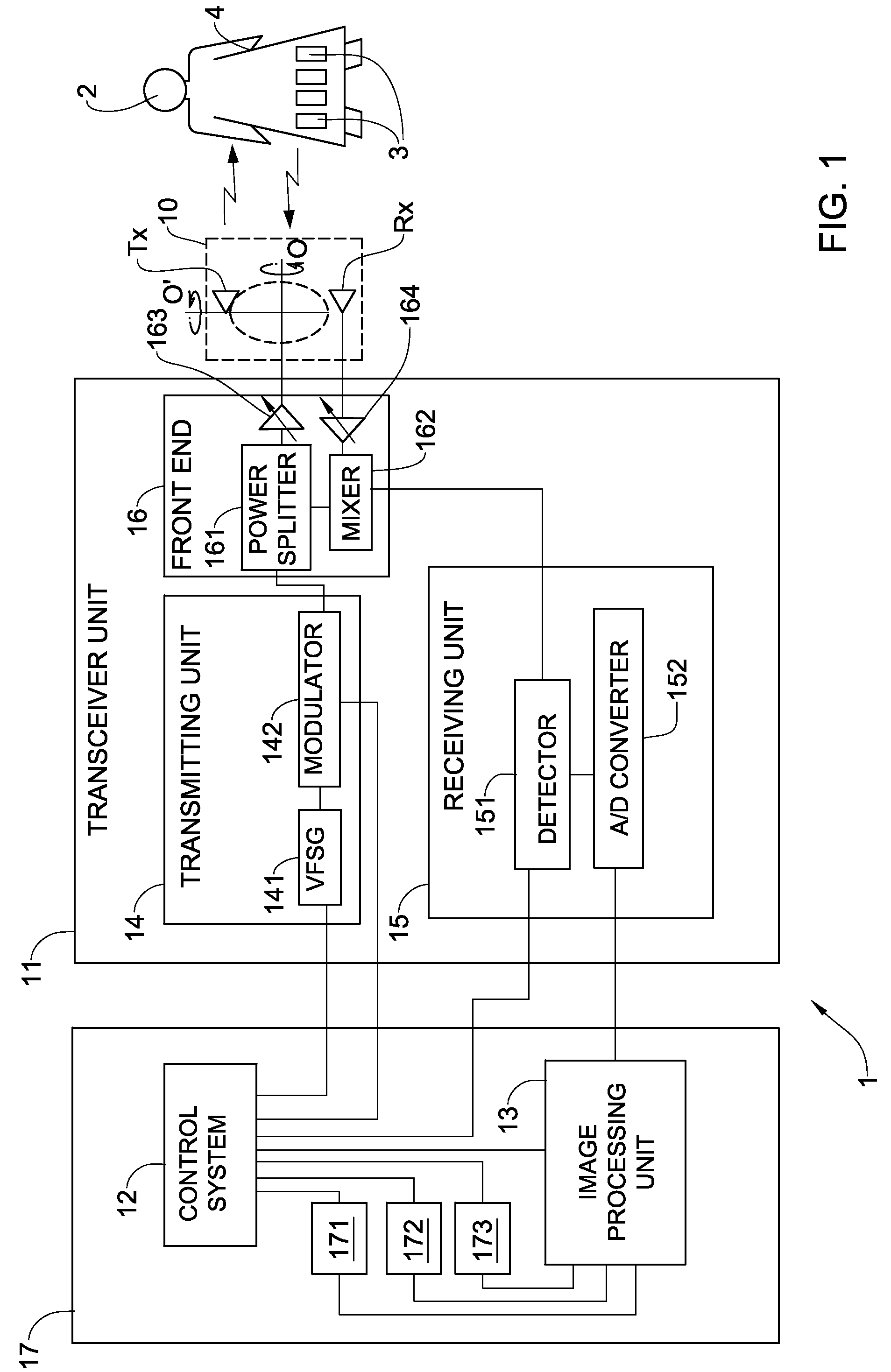
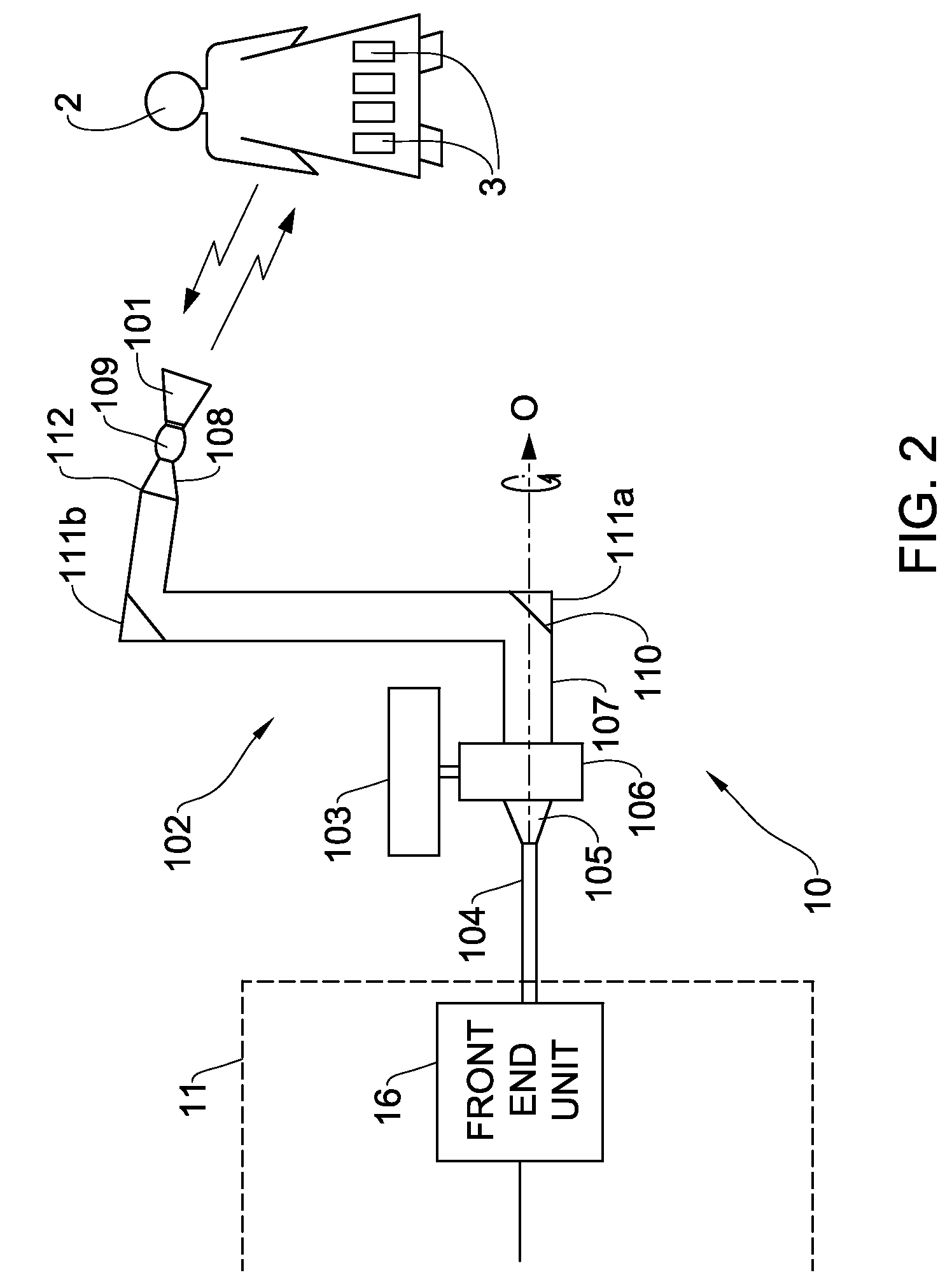
The present invention provides an improved imaging system for detecting objects on human bodies, carried in briefcases and luggage, and in packaging and storage containers. The system uses microwave signals to scan the target and can detect threat objects in real-time. It can also remote imaging of threat objects and discriminate between different types of objects. The system includes an antenna arrangement with a rotating antenna and a receiving unit with a detector and digital converter. The front-end unit includes a power splitter and mixer. The invention provides a solution for security screening applications where a person needs to be monitored.

Problems solved by technology

While such magnetic detectors are capable of detecting metal objects passing through the detector passageway, such systems cannot determine whether the detected metal object is a threat object (e.g., a knife or a gun) or an innocuous (non-threat) object (e.g., keys, coins, jewelry, belt buckles).
Moreover, these detection systems do not pinpoint the location of the metal objects on the individual's body.
Likewise, these systems are useless in detection of modern threats posed by plastic and ceramic items and plastic and liquid explosives.
Moreover, there are situations when a person under surveillance need not be aware that he or she is being monitored.
In such a case, the portal systems described above are not appropriate.
Although very effective for certain security tasks, X-ray imaging can pose a serious health risk to living organisms due to X-ray exposure, and is therefore unacceptable to the public.

Method used


Image

  • System and method for imaging objects
  • System and method for imaging objects
  • System and method for imaging objects

Examples


Embodiment Construction

[0061]The principles and operation of a system for imaging visible and concealed objects according to the present invention may be better understood with reference to the drawings and the accompanying description. It should be understood that these drawings are given for illustrative purposes only and are not meant to be limiting. It should be noted that the figures illustrating various examples of the system of the present invention are not to scale, and are not in proportion, for purposes of clarity. It should be noted that the blocks as well other elements in these figures are intended as functional entities only, such that the functional relationships between the entities are shown, rather than any physical connections and / or physical relationships. The same reference numerals and alphabetic characters will be utilized for identifying those components which are common in the imaging system and its components shown in the drawings throughout the present description of the inventi...


PUM


Abstract

An active imaging system for imaging a target is described. The system includes a transmitting unit, a receiving unit, an antenna arrangement coupled to the transmitting unit and / or the receiving unit via a front end unit, and an image processing unit coupled to the receiving unit. The system also includes a control system coupled to the transmitting unit, the receiving unit and / or the image processing unit for controlling operation thereof. The antenna arrangement includes at least one rotating antenna synthetically forming a circular antenna. The image processing unit is configured for creating an image of the object by employing a synthetic aperture radar imaging algorithm.

Description

RELATED APPLICATIONS[0001]This application is a Continuation of International Application No. PCT / IL2008 / 001219 filed on Sep. 11, 2008, which claims priority to Israeli Patent Application No. IL186884 filed on Oct. 24, 2007, both of which are incorporated herein by reference in their entirety.FIELD OF THE INVENTION[0002]The present invention relates generally to detection and imaging systems, and in particular, to radio frequency imaging systems designed to find objects carried on human bodies.BACKGROUND OF THE INVENTION[0003]In many applications it is important to find objects that are carried by people and which can be concealed on their bodies. Detection systems are known which require an individual to pass through a fixed detector passageway (portal) equipped with magnetic sensors. When metallic objects of sufficient mass pass through the passageway, a warning signal is activated because a change in magnetic flux is detected. This type of system either detects or does not detect...

Claims


Application Information

Patent Timeline
Patent Type & Authority Patents(United States)
IPC IPC(8): H01Q3/00G01S13/00H01Q3/02
CPCG01S13/003G01S13/9035G01S13/887G01S2013/9088G01S13/9088G01S13/9058
Inventor WEISS, NATHAN
Owner ELTA SYST LTD
Learn More