Video signal processing apparatus, video displaying apparatus and high resolution method for video signal
a video signal and processing apparatus technology, applied in the field of high-resolution video signals obtained from video signals, can solve the problem of only increasing the number of pixels, and achieve the effect of high-resolution video signals
- Summary
- Abstract
- Description
- Claims
- Application Information
AI Technical Summary
Benefits of technology
Problems solved by technology
Method used
Image
Examples
embodiment 1
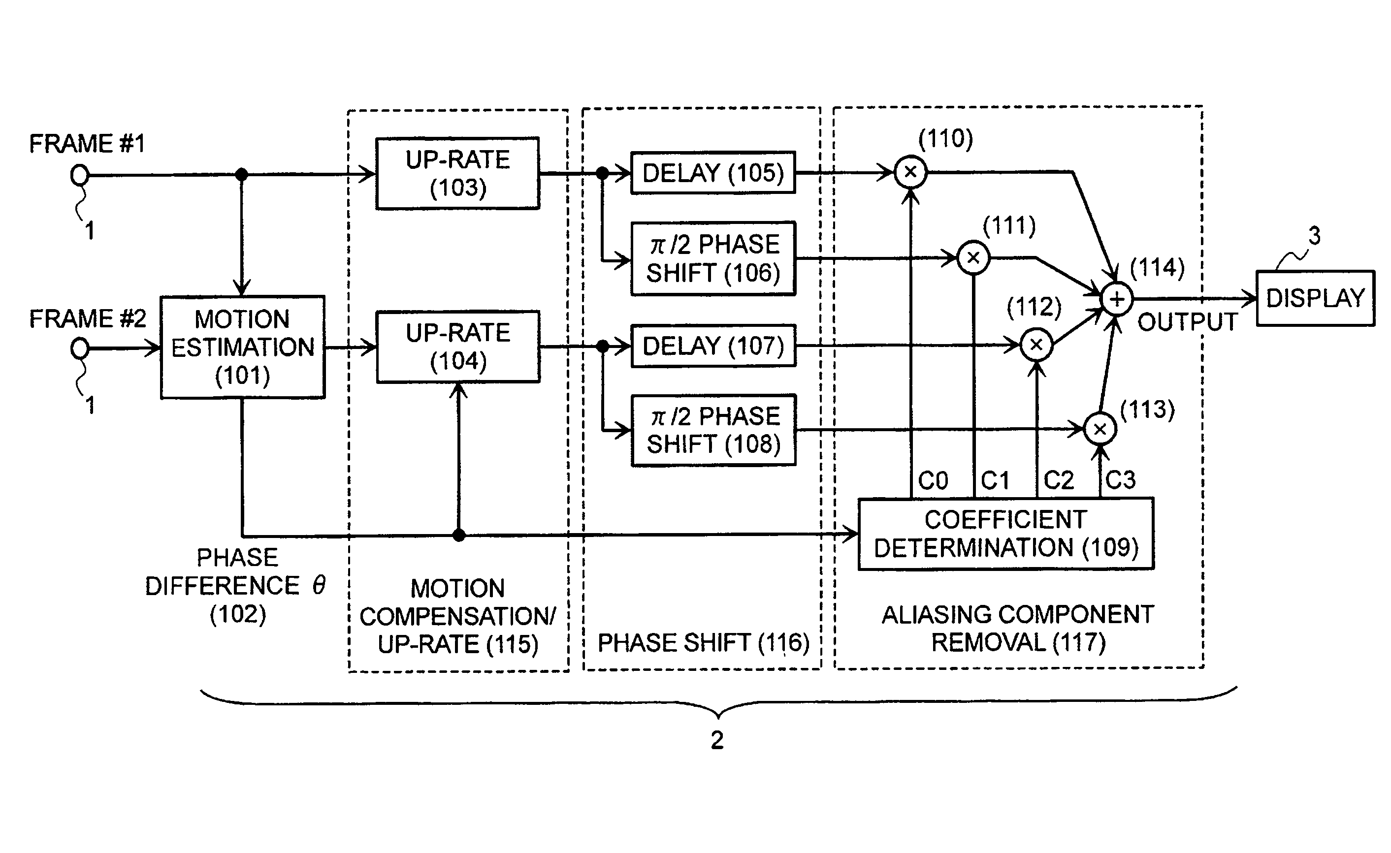
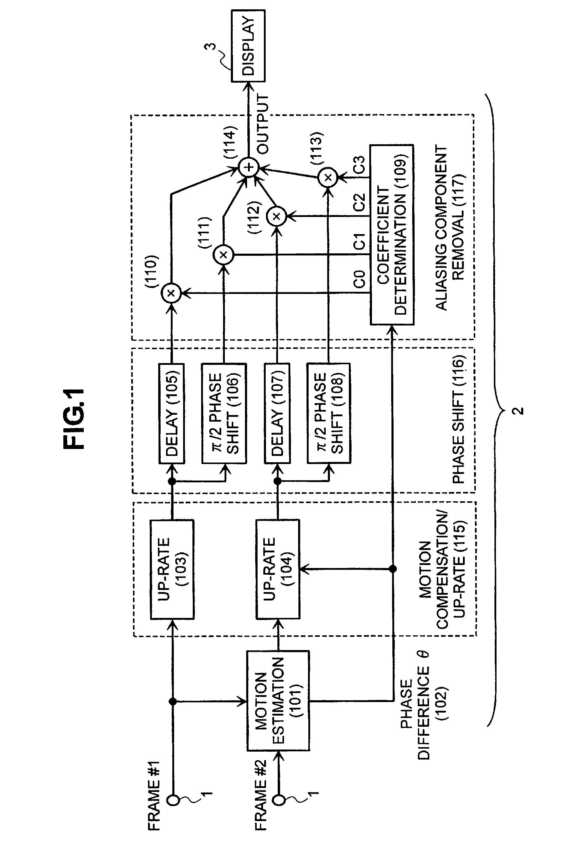
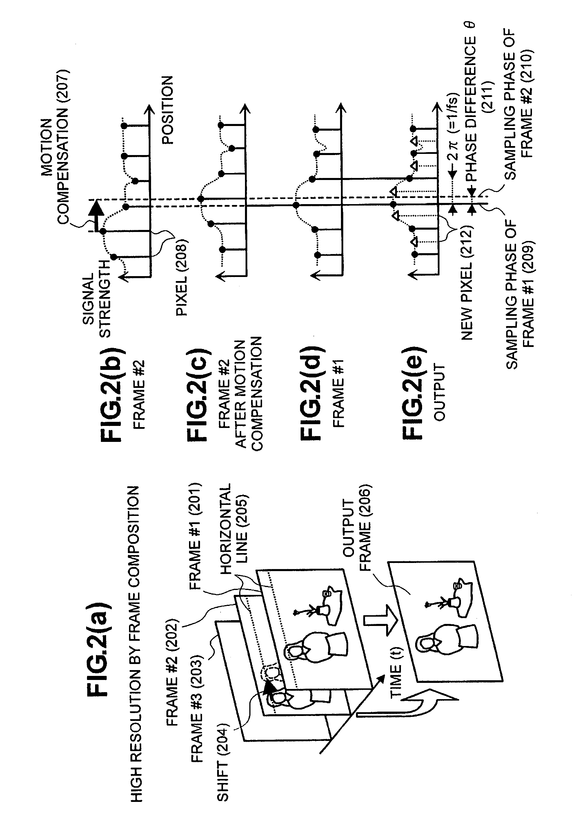
[0057]FIG. 1 shows a first embodiment of the video signal processing apparatus, according to the present invention, and the distinctive features thereof will be mentioned. The video signal processing apparatus, according to the present embodiment, will be applied into a video display apparatus, such as, a television receiver, etc., for example. In the present embodiment mentioned below, explanation will be made on the example of the video display apparatus, as the video signal processing apparatus. In FIG. 1, the video signal processing apparatus, according to the present embodiment, comprises an input portion 1, into which are inputted a frame line of moving pictures, such as, a television broadcast signal or the like, for example, a resolution converter portion 2 for obtaining high resolution of frames, which are inputted from that input portion, and further a display portion for displaying a picture upon basis of the frames, which are high resolved within that resolution converte...
embodiment 2
[0069]FIG. 10 shows a second embodiment according to the present invention. The structures shown in this figure are obtained by simplifying the structures shown in FIG. 1, with using the relationship among the coefficients C0, C1, C2 and C3 shown in FIG. 9(c). Thus, since C0=C2=½ and C1=−C3=−(1+cos θ) / 2 sin θ, the signals of sum and difference are produced by means of an adder (1001) and a subtractor (1004), from the frame #1 and the frame #2 after the motion compensation and up-rating. With the sum signal, after passing through a fs cut-off filter (1002), it is inputted into an adder (1008) with multiplying by C0 (=0.5) within a multiplier (1003). Herein, the fs cut-off filter (1002) is for cutting off the components of the sampling frequency (fs) before up-rating as a zero point, and it can be achieved by using the tap coefficients shown in (1011) of FIG. 10, for example. The propose of providing this fs cut-off filter (1002) lies to prevent unnecessary component of frequency fs f...
embodiment 3
[0071]FIG. 11 shows a third embodiment according to the present invention. The structures shown in this figure is constructed upon basis of the structures shown in FIG. 10, enabling to change an output from an auxiliary pixel compensation portion (1105) when the phase difference θ comes close to zero (0), for the purpose of preventing the coefficients C1 and C3 from becoming unstable when the phase difference θ is zero (0), as shown in FIG. 9(d), and / or preventing the coefficients C1 and C3 from becoming weak against noises due to becoming large as the phase difference θ comes close to zero (0). Thus, a general interpolation low-pass filter (1101) is prepared as a bypass route, while C4 is newly produced other than the above-mentioned coefficients C0 and C1 within the coefficient determining portion (1103), and an output of the interpolation low-pass filter (1101) is multiplied by the coefficient C4 within the multiplier (1102), and thereafter it is outputted after being added onto ...
PUM
 Abstract
Description
Claims
Application Information
 - R&D
- Intellectual Property
- Life Sciences
- Materials
- Tech Scout
- Unparalleled Data Quality
- Higher Quality Content
- 60% Fewer Hallucinations
Browse by: Latest US Patents, China's latest patents, Technical Efficacy Thesaurus, Application Domain, Technology Topic, Popular Technical Reports.
© 2025 PatSnap. All rights reserved.Legal|Privacy policy|Modern Slavery Act Transparency Statement|Sitemap|About US| Contact US: help@patsnap.com


