
Mobile communication system, receiving device, and method

a mobile communication system and receiving device technology, applied in the field of mobile communication technologies, can solve the problems of increasing multipath interference, multipath interference becoming particularly prominent, and multipath interference tending to occur, so as to improve signal detection accuracy

Inactive Publication Date: 2012-11-27
NTT DOCOMO INC
View PDF13 Cites 8 Cited by
  • Summary
  • Abstract
  • Description
  • Claims
  • Application Information

AI Technical Summary

Benefits of technology

The present invention relates to a mobile communication system that uses a single-carrier MIMO transmission scheme and a single-carrier FDMA approach for efficient data transmission. The invention aims to improve signal detection accuracy at the receiving end, which can be challenged due to the high peak power ratio and multipath interference in this transmission scheme. The invention provides a solution by introducing a decomposing unit that obtains a triangular matrix and a vector to estimate the symbols transmitted from the transmitting antennas. This approach helps to improve signal detection accuracy and reduce computational complexity for signal detection.

Problems solved by technology

Meanwhile, with single-carrier transmission schemes where subcarriers with a relatively large bandwidth are used, multipath interference tends to occur.
Multipath interference increases as the transmission rate increases.
For example, multipath interference becomes particularly prominent when the data modulation level is high or a MIMO multiplexing scheme is used.
Increase in multipath interference in turn reduces the detection accuracy of signals at the receiving end.
Thus, with a single-carrier transmission scheme, the number of candidates increases exponentially according to the number of multipaths and as a result, the computational complexity for signal detection increases.
This in turn makes it difficult to employ an MLD method, which provides high detection accuracy but require high computational complexity, together with a single-carrier MIMO transmission scheme.
Signal detection methods such as a zero forcing (ZF) method and a minimum mean squared error (MMSE) method require low computational complexity, but may reduce the signal detection accuracy.
However, since one purpose of employing a single-carrier transmission scheme is to reduce the PAPR and thereby to save battery energy, it is not preferable to increase the transmission power.

Method used


Image

  • Mobile communication system, receiving device, and method
  • Mobile communication system, receiving device, and method
  • Mobile communication system, receiving device, and method

Examples


first embodiment

1. System

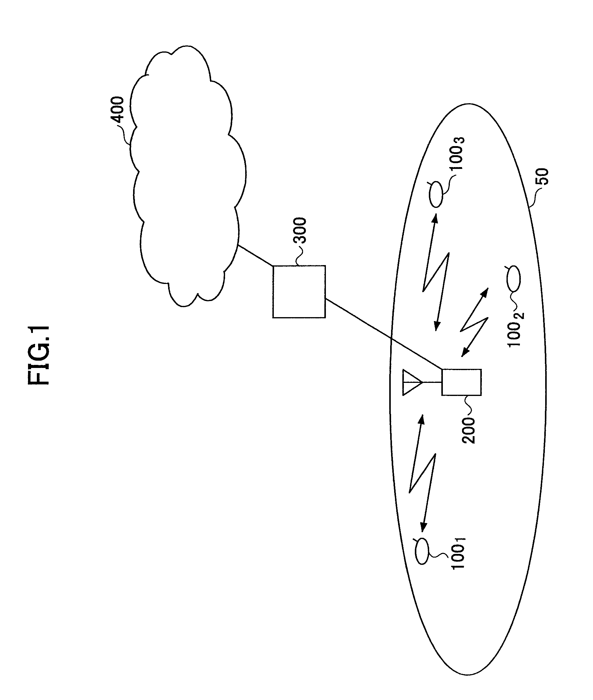
[0058]FIG. 1 shows a mobile communication system according to an embodiment of the present invention. As shown in FIG. 1, the mobile communication system includes a cell 50, user devices 1001, 1002, and 1003 (may be collectively called the user device 100) in the cell 50, a base station 200, an access gateway 300, and a core network 400. In this embodiment, it is assumed that one or more of the user devices 1001, 1002, and 1003 perform radio communications with the base station 200 according to a MIMO scheme. The user device 100 is typically a mobile station, but may instead be implemented as a fixed station. It is also assumed that the mobile communication system employs SC-FDMA (or DFT-spread OFDM) for uplink. Alternatively, the mobile communication system may employ SC-FDMA for downlink.

2. Transmitting Device

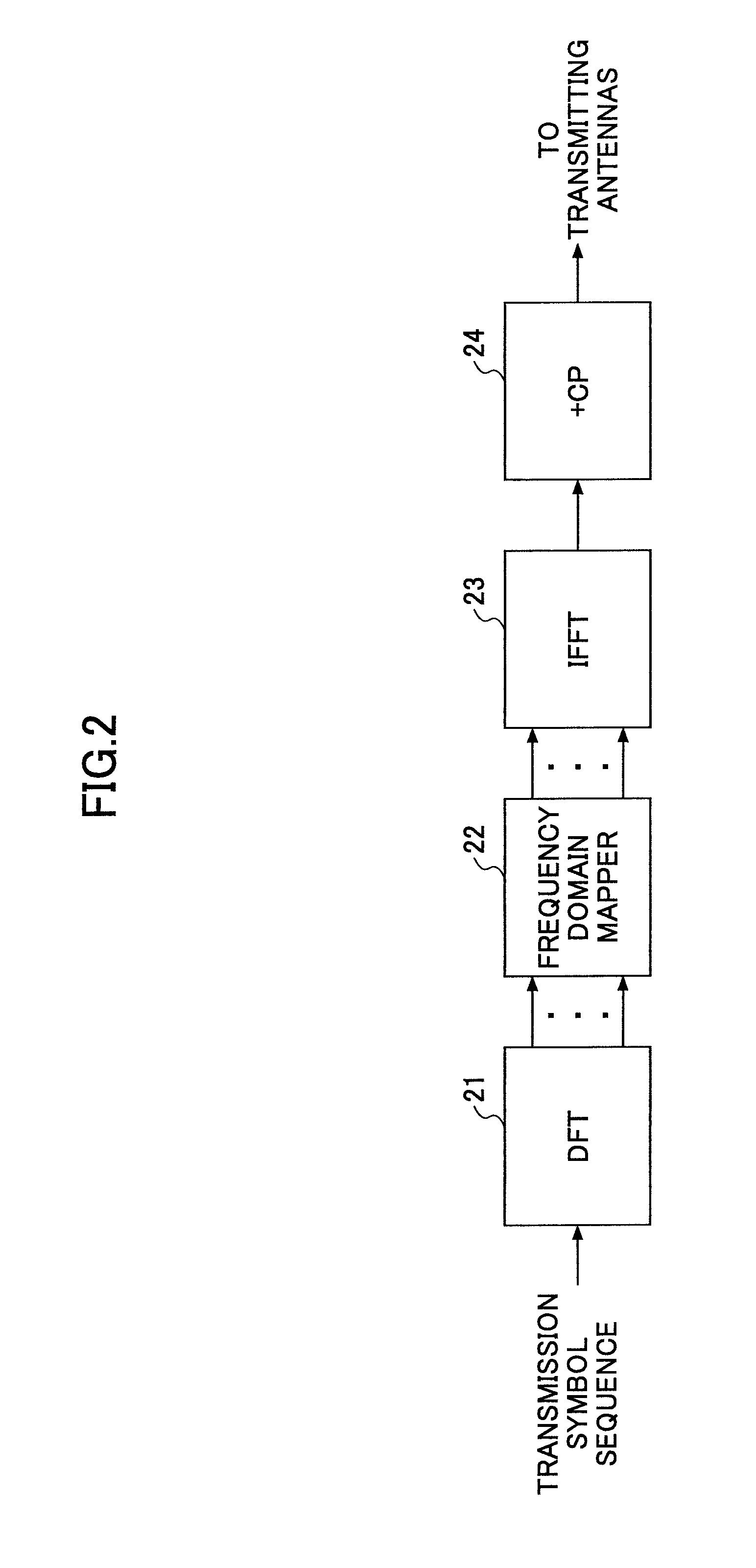
[0059]FIG. 2 shows a transmitting device for the mobile communication system of this embodiment. In this embodiment, it is assumed that the transmitting device is in...


PUM


Abstract

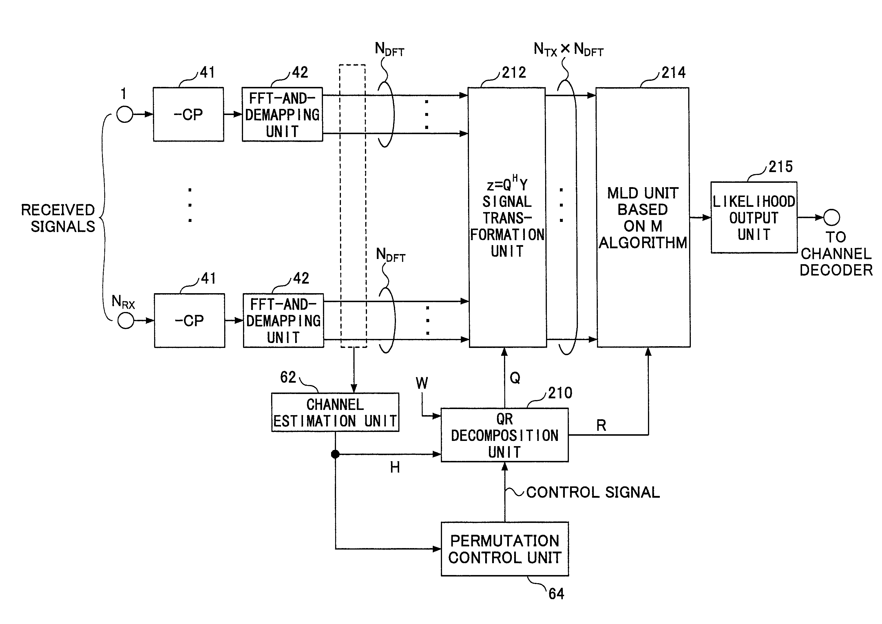
A transmitting device Fourier-transforms symbols in a transmission symbol sequence, maps the Fourier-transformed symbols to subcarriers, inverse-Fourier-transforms the mapped symbols, and transmits the inverse-Fourier-transformed symbols from multiple transmitting antennas. A receiving device Fourier-transforms received signals, extracts signal components mapped to the subcarriers, and estimates the symbols transmitted via the subcarriers by applying a QR decomposition algorithm to the extracted signal components. The receiving device obtains a unitary matrix QH such that the product of the unitary matrix QH, a weight matrix W determining a correspondence between the transmission symbol sequence and the subcarriers, and a channel matrix H becomes a triangular matrix R, and estimates candidates of the symbols transmitted from the transmitting antennas based on the unitary matrix QH and the triangular matrix R.

Description

TECHNICAL FIELD[0001]The present invention generally relates to mobile communication technologies. More particularly, the present invention relates to a mobile communication system, a receiving device, and a method adapted for single-carrier multiple input multiple output (MIMO) transmission.BACKGROUND ART[0002]In multicarrier transmission schemes, a frequency band is divided into multiple narrow frequency bands (subcarriers) and separate signals are transmitted using the subcarriers. For example, in orthogonal frequency division multiple access (OFDMA), subcarriers are arranged such that they become orthogonal to each other to improve frequency efficiency and to achieve high-speed, high-volume communications. OFDMA makes it possible to effectively reduce inter-subcarrier interference. This in turn makes it possible to concurrently transmit signals using subcarriers and to increase the symbol length. Also with OFDMA, it is possible to effectively reduce multipath interference by usi...

Claims


Application Information

Patent Timeline
Patent Type & Authority Patents(United States)
IPC IPC(8): H04L27/06
CPCH04B7/0413H04L25/0246H04J11/0046H04L27/2647H04L25/0204H04L25/03159H04L25/03216H04L25/03891
Inventor HIGUCHI, KENICHI
Owner NTT DOCOMO INC
Learn More