
Faux brick with suspension system

Inactive Publication Date: 2012-12-04
KOWNACKI CHARLES D
View PDF17 Cites 20 Cited by
  • Summary
  • Abstract
  • Description
  • Claims
  • Application Information

AI Technical Summary

Benefits of technology

[0002]Currently, if a builder or homeowner wants a house sporting the look of brick, s / he has basically two options: actual masonry construction, or installing a face brick utilizing a suspension grid. These systems are hard to install, are comparatively expensive and involve heavy construction materials. It is an object of the present invention to provide a monolithic, light-weight thin-walled composite panel configured to look like brick. Many composite siding systems suffer from the problem of trapping moisture behind the panel which provides a breeding ground for mold growth. The suspension system of the present invention provides adequate standoff from the attachment substrate to permit airflow which dries out any moisture which finds its way behind the panels, preventing mold growth.
[0005]The first vertical arm has a series of cutouts to reduce an amount of material utilized in making the H-shaped channel. The series of cutouts includes a first group of upper cut outs and a second group of lower cutouts. The second vertical arm comprises a first set of upwardly directed arm sections extending upwardly from the first horizontal arm opposite the first group of upper cutouts. The second vertical arm further comprises a second set of downwardly directed arm sections extending downwardly from the first horizontal arm opposite the second group of lower cutouts. The first set of upwardly directed arm sections engage lower portions of a first set of siding panels restraining their movement along the z-axis, while the second set of downwardly directed arm sections engage upper portions of a second set of siding panels restraining their movement along the z-axis.
[0006]Another aspect of the invention includes a siding system comprising a) a light-weight, monolithic composite panel, the monolithic composite panel having thin walls configured to give the appearance of three-dimensional brick having a dimension along each of an x-axis, a y-axis and a z-axis; b) a suspension system for attaching the light-weight, monolithic composite panel to a substrate, the suspension system spacing the monolithic composite panel from the substrate preventing movement along the y-axis and the z-axis while allowing lateral movement along the x-axis. The panel includes a series of rows of bricks, adjacent the rows of bricks having varying lengths forming spaces, whereby an adjacent composite panel will have offset simulated bricks which interdigitate with said spaces. A specialty panel for corners is provided having a first group of simulated bricks extending in a first direction and a second group of simulated bricks extending in a second orthogonal direction.

Problems solved by technology

These systems are hard to install, are comparatively expensive and involve heavy construction materials.
Many composite siding systems suffer from the problem of trapping moisture behind the panel which provides a breeding ground for mold growth.

Method used


Image

  • Faux brick with suspension system
  • Faux brick with suspension system
  • Faux brick with suspension system

Examples


Embodiment Construction

)

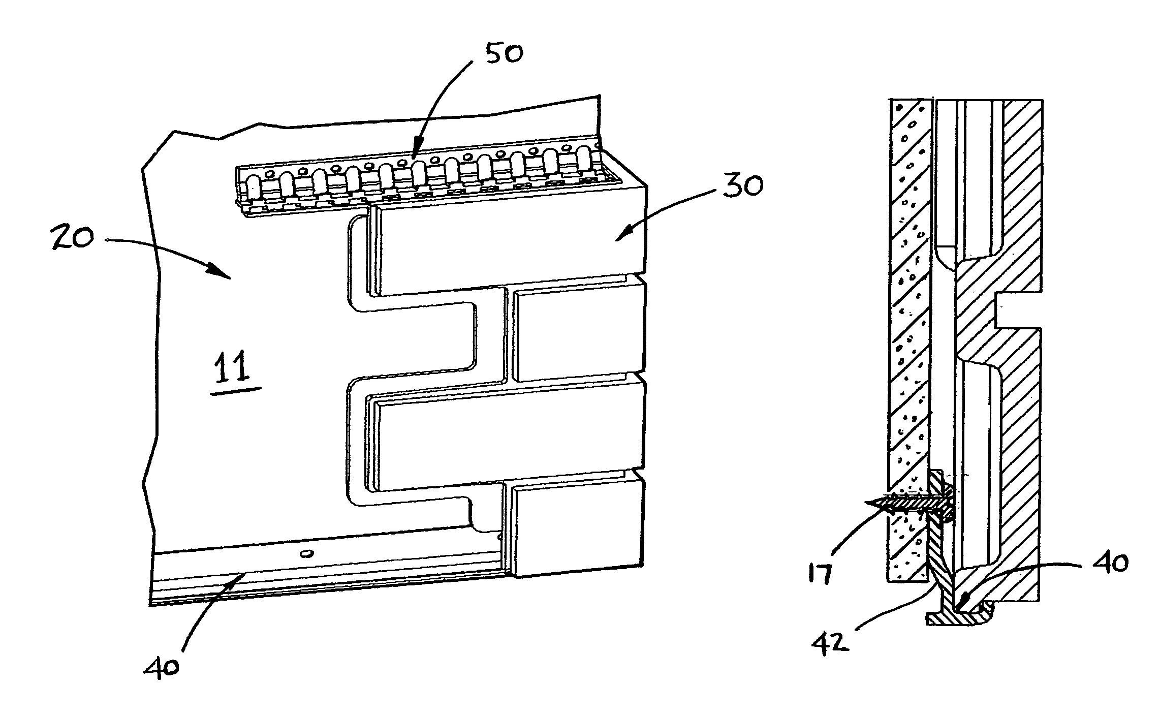
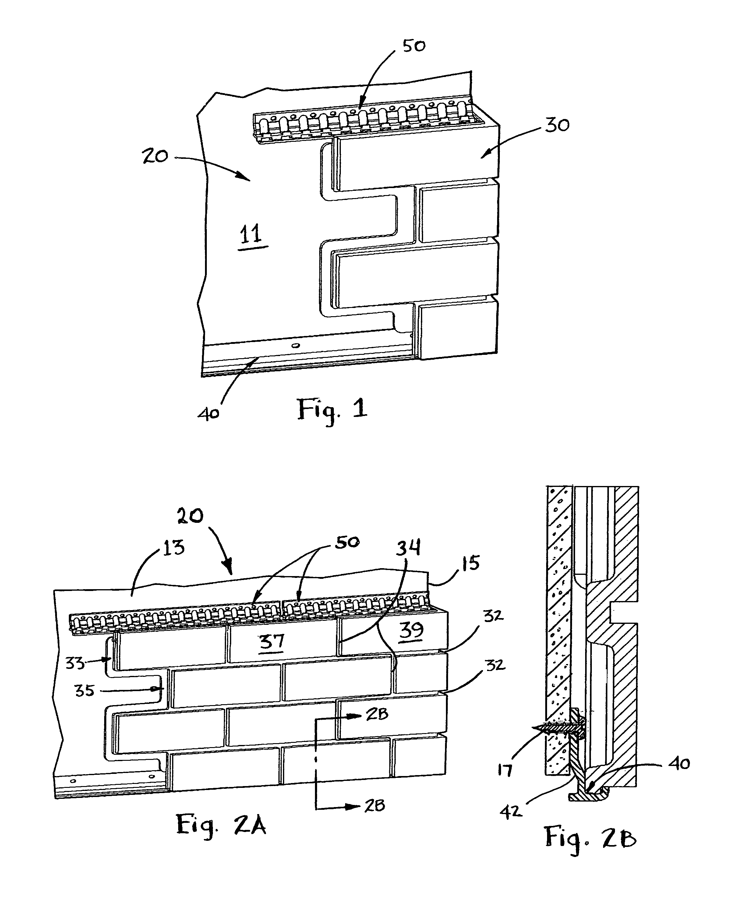
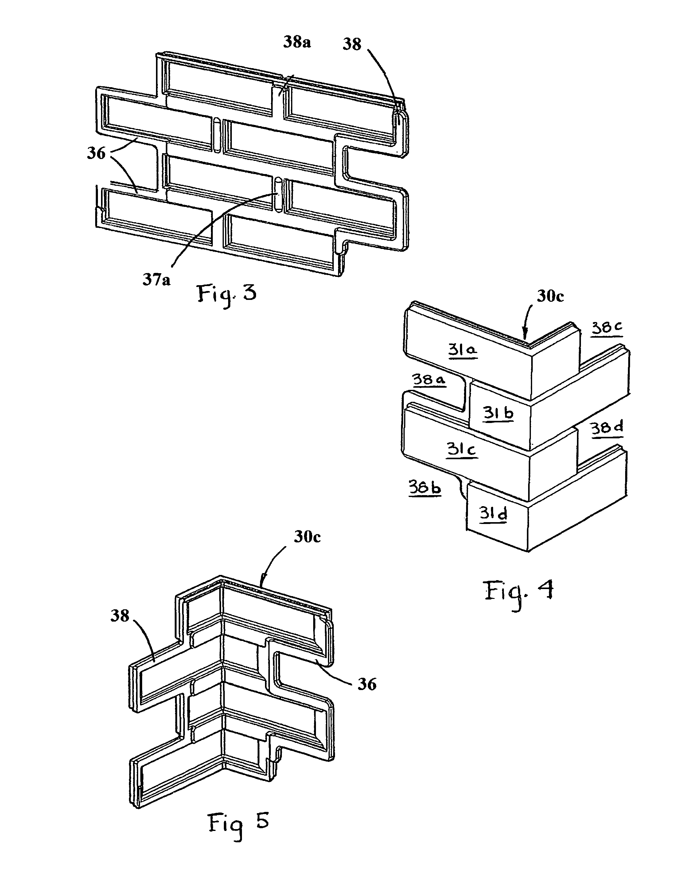
[0018]A first embodiment of the faux brick with suspension system of the present invention is depicted in FIGS. 1-2 generally at 20. Faux brick with suspension system 20 includes a thin, light-weight monolithic panel 30 secured to a substrate 11 using a J-channel 40 and an H-shaped channel 50. The panel 30 is molded to simulate a brick appearance having longitudinally extending recesses 32 to mimic the space between adjacent courses 33, 35 of bricks (FIG. 2A) and vertically extending recesses 34 to simulate the spaces between one brick 37 and an adjacent brick 39 in the same course. Both the front and the back of each panel 30 has three levels. As best seen in FIG. 3, the longitudinally extending recesses 32 are broadened on the back side as at 36 as are the vertical recesses as at 38 to effectively reinforce the monolithic panel 30 giving it some stiffness. An intermediate level 38a extends between 36 and 38 and extends around most of the rear surfaces of bricks 39a. The panels 30...


PUM


Abstract

A suspension system secures thin, light-weight, monolithic panels which appear as adjacent courses of brick to be suspended adjacent a substrate in a manner permitting sliding movement in the x-direction while inhibiting motion in the y- and z-directions, and, such that air can circulate behind the panel to prevent mold growth. The primary suspension hardware is an H-shaped channel with two vertically extending arms which secure the panels at the desired spaced position from the substrate.

Description

BACKGROUND AND SUMMARY OF THE INVENTION[0001]The present invention is directed to building construction. More particularly, the present invention is directed to a thin-walled monolithic panel with a suspension system to attach it to, and stand it off from, a substrate.[0002]Currently, if a builder or homeowner wants a house sporting the look of brick, s / he has basically two options: actual masonry construction, or installing a face brick utilizing a suspension grid. These systems are hard to install, are comparatively expensive and involve heavy construction materials. It is an object of the present invention to provide a monolithic, light-weight thin-walled composite panel configured to look like brick. Many composite siding systems suffer from the problem of trapping moisture behind the panel which provides a breeding ground for mold growth. The suspension system of the present invention provides adequate standoff from the attachment substrate to permit airflow which dries out any...

Claims


Application Information

Patent Timeline
IPC IPC(8): E04B2/90E04B2/82
CPCE04F13/0733E04F13/0803E04F13/147
Inventor KOWNACKI, CHARLES D
Owner KOWNACKI CHARLES D
Learn More