Automatic sampling and dilution apparatus for use in a polymer analysis system

a polymer analysis and automatic sampling technology, applied in the field of absolute characterization of microscopic particles in solution, can solve the problems of long delay time in obtaining, insufficient continuous record of reaction, and inconvenient use, and achieve the effect of reducing the viscosity of the polymer

Active Publication Date: 2012-12-04
THE ADMINISTRATORS OF THE TULANE EDUCATIONAL FUND
View PDF32 Cites 20 Cited by
  • Summary
  • Abstract
  • Description
  • Claims
  • Application Information

AI Technical Summary

Benefits of technology

[0026]The present invention can be used in several distinct modes (immersion, fill mode, insert mode and flow mode), giving it wide versatility. The probe of the present invention is not constrained to be immersed in order to function. A small quantity of sample can also be placed in the optical assembly compartment for measurement in a ‘fill mode’. A sample in a transparent vial or cell can also be placed in the chamber or ring member for measurement. Also, the probe can be hooked into a flowing stream of sample liquid for use in different applications such as polymer separation (e.g. size exclusion chromatography), and on-line, unfractionated flows of polymers in a vessel in equilibrium, or undergoing polymerization, aggregation, cross-linking or degradation processes.
[0052]Because all the pumps used are potentially controllable by a programmable logic controller, personal computer, palm pilot, or other electronic device containing a microprocessor the ability to control both the dilution factor and various flow rates is straightforward.

Problems solved by technology

This, however, leads to long delay times in obtaining results, usually too long to make useful adjustments to the reaction.
Such manual sampling also does not yield a continuous enough record of the reaction to follow the time course quantitatively.
There can also be safety issues involved when workers expose themselves to hazardous reactor environments to obtain samples.
The single greatest problem in the practical use of ACOMP is the automatic, continuous preparation of the mixed or diluted sample which continuously feeds the detector train.
The problem is due chiefly to the high viscosities which develop during many polymerization reactions, as well as the bubbles that can occur.
The problem with these devices is that they are designed and built to handle only low viscosity liquids.
When one of the feeds to a low pressure mixing pump is a reactor whose viscosity increases during a polymerization reaction, the mixing pump is incapable of maintaining a fixed volume withdrawal rate percentage.
The result is that the lag time between withdrawal from the reactor and arrival of the mixed solution at the detectors becomes longer and longer as the reaction proceeds, often times to unacceptable levels.
When a high pressure mixing scheme is used, bubbles produced either by the reaction itself, or due to cavitation during pump withdrawal, lead to the depriming of the withdrawal pump, and failure to continue monitoring.
The check valves and other plumbing in such pumps is also susceptible to becoming frozen by plugs of polymeric material that can solidify in the pumps during operation.
It is apparent that pumps that rely on pulling reactor material with a vacuum (1 atmosphere or less) are wholly unsuitable for ACOMP when viscosities are above about 150 centipoise (cP); i.e. arrangements of such pumps can typically follow a reaction from about 1 cP to about 150 cP.
Whereas this latter technology is highly developed for industries involving, for example, plastic injection and synthetic fiber production, there is no available system that can accomplish the prerequisite of ACOMP: Continuously withdraw a very small flow rate of material and mix it homogeneously with a solvent.

Method used


Image

  • Automatic sampling and dilution apparatus for use in a polymer analysis system
  • Automatic sampling and dilution apparatus for use in a polymer analysis system
  • Automatic sampling and dilution apparatus for use in a polymer analysis system

Examples


specific embodiments

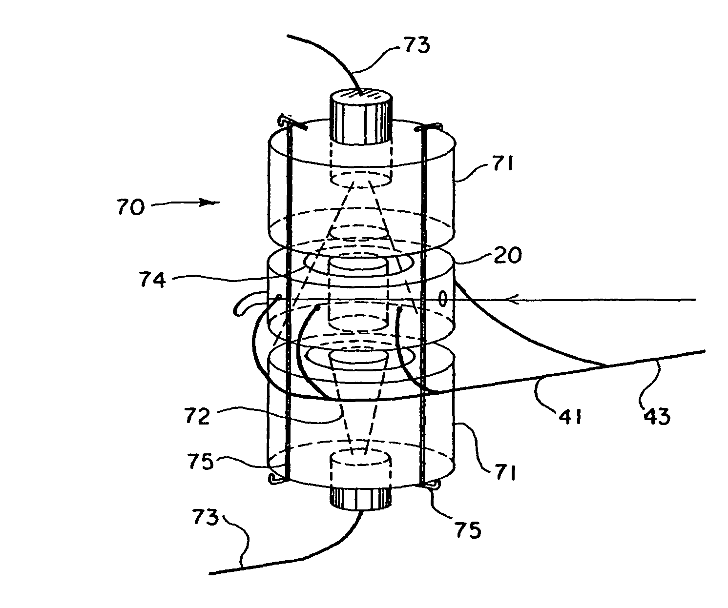
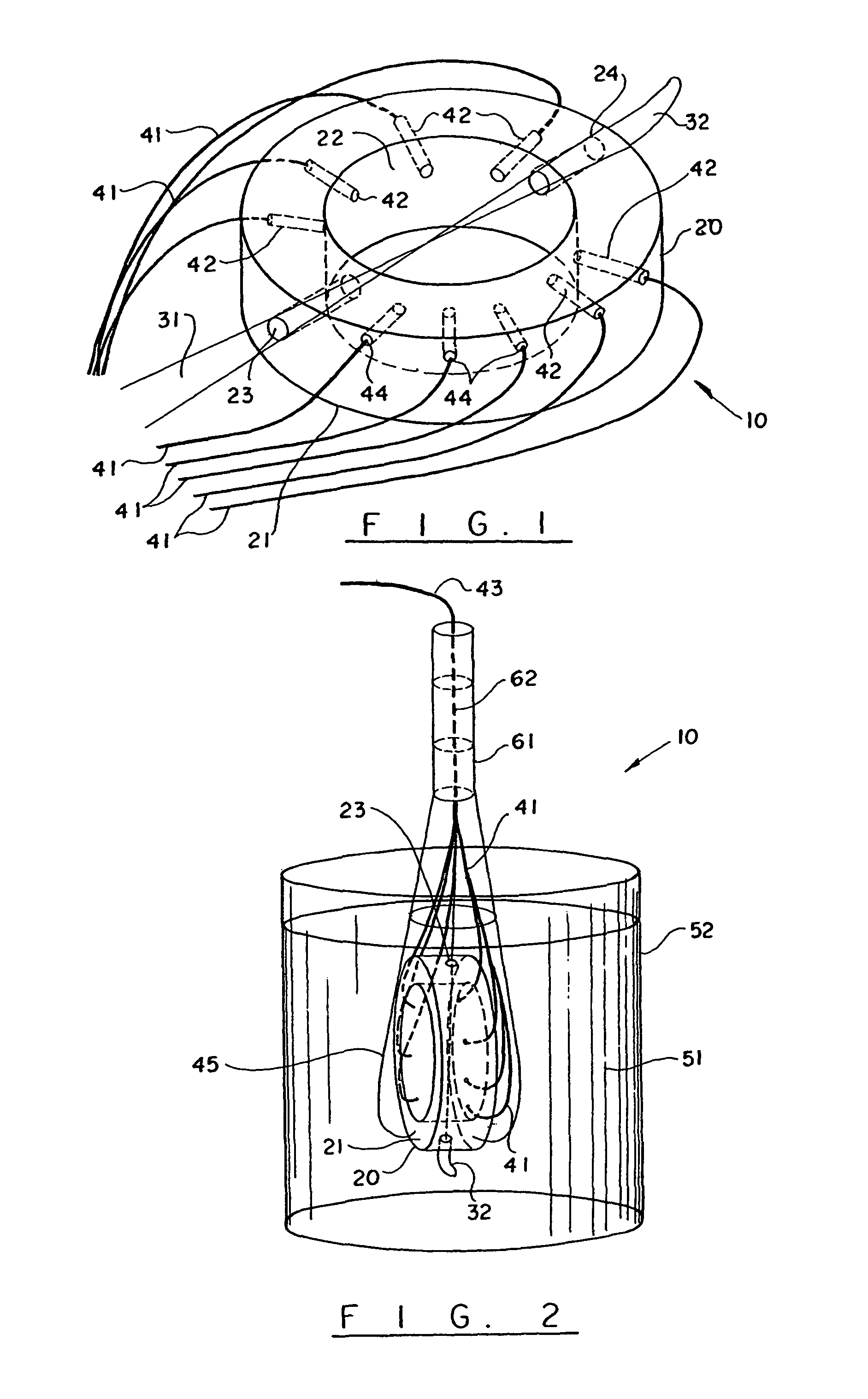
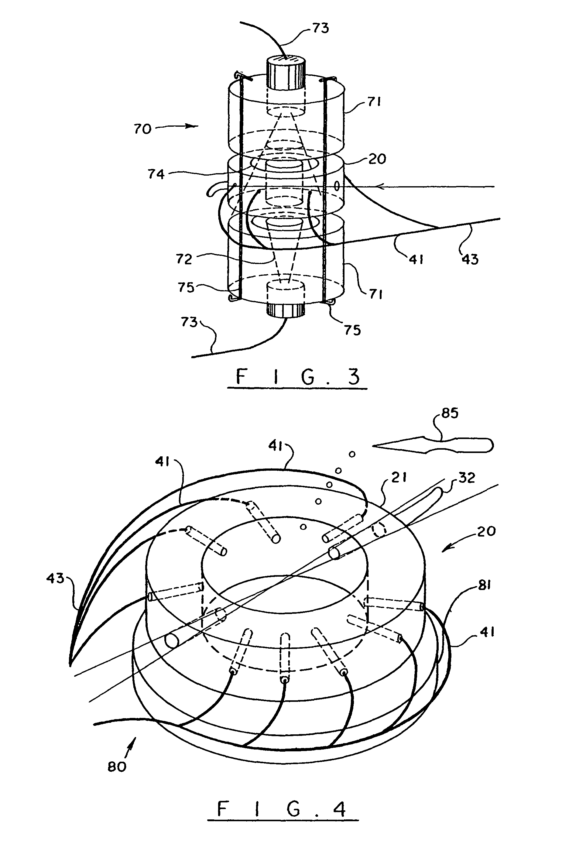
[0215]The device consists of the following elements: A pump for withdrawing liquid from the polymer vessel, a pump for withdrawing solvent from a solvent reservoir, a scheme for homogeneously mixing the reactor contents and the solvent, and a means of pumping the mixed solution to the detector train. Often times a secondary dilution stage will be used to achieve even higher levels of dilution than is feasible with a single stage.

[0216]Means of withdrawing the liquid from the reactor preferably include, but are not limited to, peristaltic, lobe, gear and screw pumps, and their variants, and certain specialty piston pumps (such as are commercially available from Fluid Metering, Inc. of Syosset, N.Y.). Means of pumping solvent include any of the above mentioned pumps, but also piston and other pumps suitable for pumping low viscosity liquids. Means for homogeneously mixing include micro-mixing ‘T’ type chambers, actively stirred microchambers, mixing chambers with static mixing element...


PUM

PropertyMeasurementUnit
viscosityaaaaaaaaaa
sizeaaaaaaaaaa
sizeaaaaaaaaaa

Abstract

The present invention provides an automatic sampling and dilution apparatus for use in a polymer analysis system. The apparatus comprises (a) a primary mixing chamber; (b) a primary pump capable of continuously withdrawing a variable viscosity liquid from a reactor at a selectable, fixed withdrawal rate over a varying viscosity range of about 50 to about 5,000,000 centipoise (cP) for continuously conveying the variable viscosity polymer-containing liquid into the primary mixing chamber; (c) a first dilution pump for continuously delivering a first dilution solvent into the primary mixing chamber at a selectable, fixed flow rate to mix with the variable viscosity liquid in the mixing chamber and thereby form a diluted polymer-containing liquid therein; and (d) a secondary pump for continuously conveying the diluted polymer-containing liquid into a flow-through detector. A polymer analysis system utilizing the automatic sampling and dilution apparatus is also provided.

Description

CROSS-REFERENCE TO RELATED APPLICATIONS[0001]This application is a continuation of U.S. application patent Ser. No. 10 / 442,676, filed on May 21, 2003, now abandoned which claims the benefit of U.S. Provisional Application Ser. No. 60 / 382,213, filed on May 21, 2002, both of which are incorporated herein by reference.STATEMENT OF GOVERNMENT INTEREST[0002]This invention was made with U.S. government support under Grant No. CTS0124006, awarded by the National Science Foundation. The US government has certain rights in this application.BACKGROUND OF THE INVENTION[0003]1. Field of the Invention[0004]The present invention relates to the absolute characterization of microscopic particles in solution. More particularly, the present invention relates to the absolute characterization of microscopic particles, such as polymers and colloids using static light scattering (SLS) and time-dependent static light scattering (TDSLS). In principle, the size range of detectability should run from about 2...

Claims


Application Information

Patent Timeline
Patent Type & Authority Patents(United States)
IPC IPC(8): G01N1/00G01N15/00G01N15/02G01N15/14G01N21/49G01N21/51G01N21/53G01N30/02G01N30/46G01N30/74G01N35/08
CPCG01N15/0211G01N15/14G01N15/1434G01N21/49G01N21/51G01N30/74G01N35/08G01N35/085G01N35/1097G01N21/53G01N30/02G01N2011/0046G01N2015/0092G01N2015/0216G01N2015/025G01N2015/0693G01N2021/4711G01N2021/4716G01N2021/4719G01N2021/513G01N2201/0218B01D15/34G01N31/16G01N33/00
Inventor REED, WAYNE F.
Owner THE ADMINISTRATORS OF THE TULANE EDUCATIONAL FUND
Why Eureka
Try Eureka