
Drilling rig and drilling method

Inactive Publication Date: 2012-12-04
BAUER MASCH GMBH
View PDF16 Cites 5 Cited by
  • Summary
  • Abstract
  • Description
  • Claims
  • Application Information

AI Technical Summary

Benefits of technology

[0008]The object underlying the present invention is to provide a drilling rig and a drilling method, by means of which bore holes can also be efficiently created with the aid of continuous screw augers beyond the length of the latter, whilst ensuring good quality of the bore holes.

Problems solved by technology

Thus earth material can no longer accumulate inside the bore hole and therefore lead to choking.
This considerably accelerates the creation of a bore hole of increased depth and additionally reduces the quantity of excavated material to be hauled away.

Method used


Image

  • Drilling rig and drilling method
  • Drilling rig and drilling method
  • Drilling rig and drilling method

Examples


Embodiment Construction

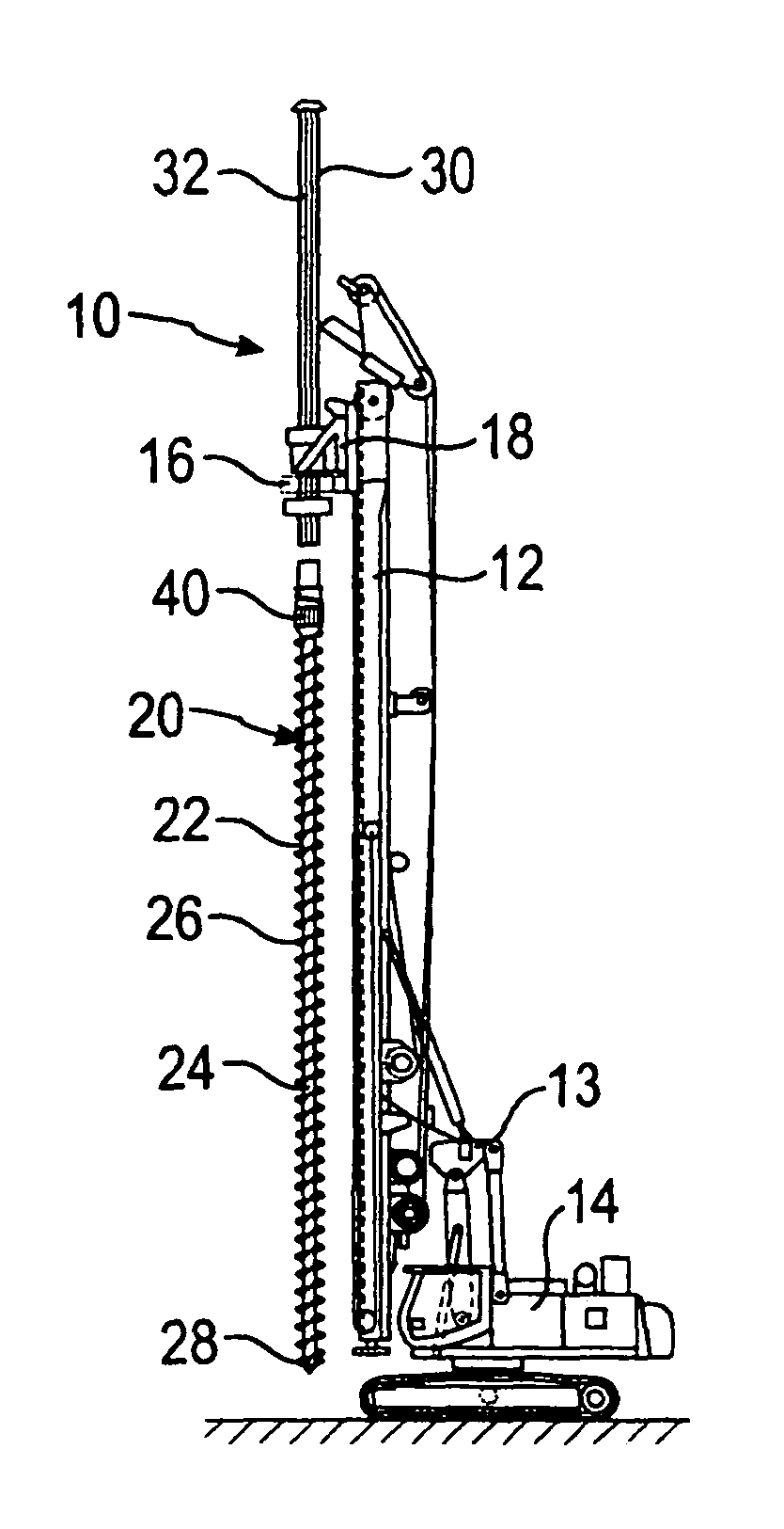
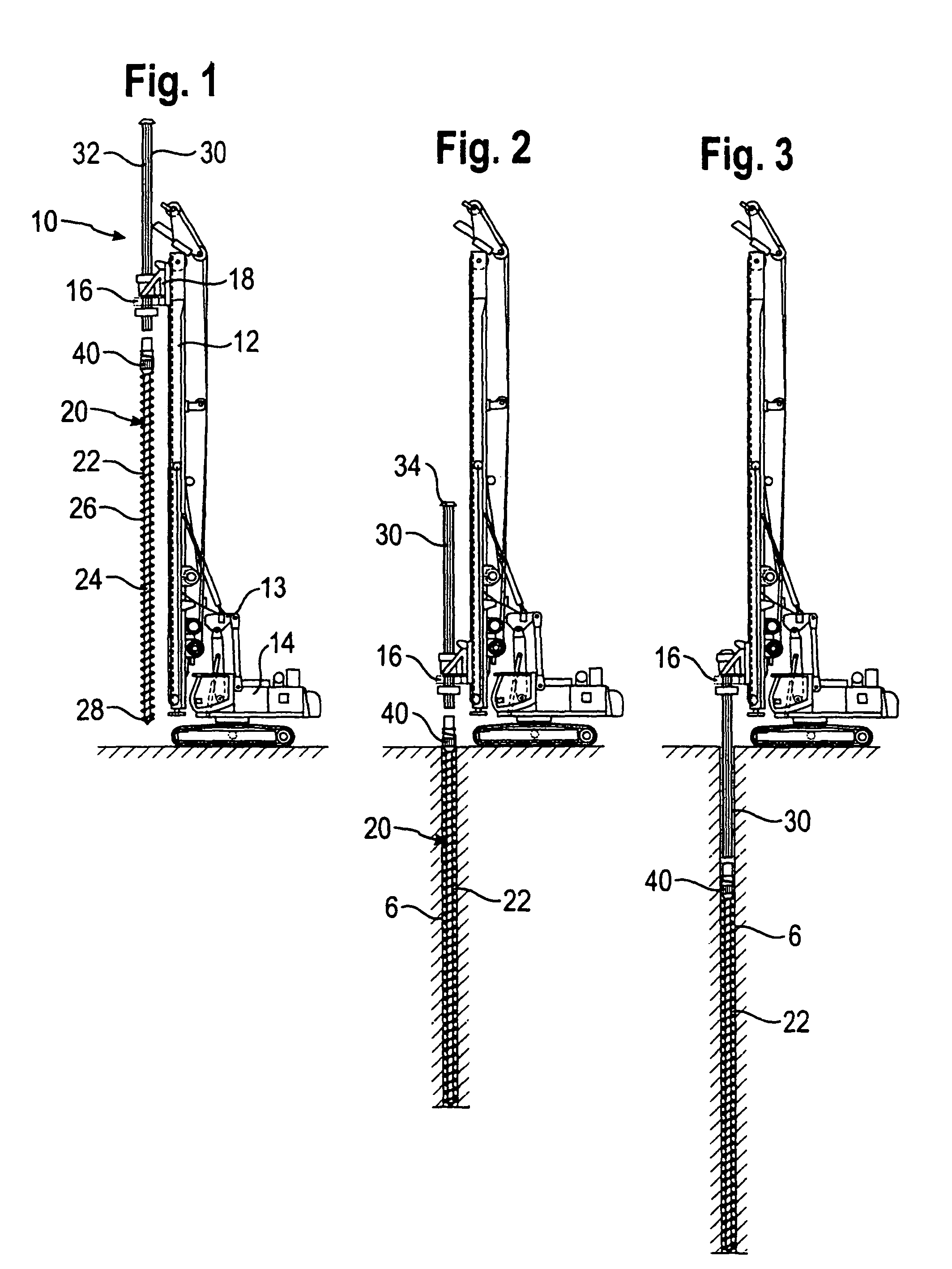
[0031]A drilling method of the invention together with a drilling rig 10 of the invention is illustrated in FIGS. 1 to 3. As shown in FIG. 1, the drilling rig 10 comprises an approximately vertically aligned mast 12, which is pivotally mounted via an adjusting mechanism 13 on a base 14. The base 14 is in the present exemplary embodiment in the form of a crawler type vehicle having a rotatable superstructure.

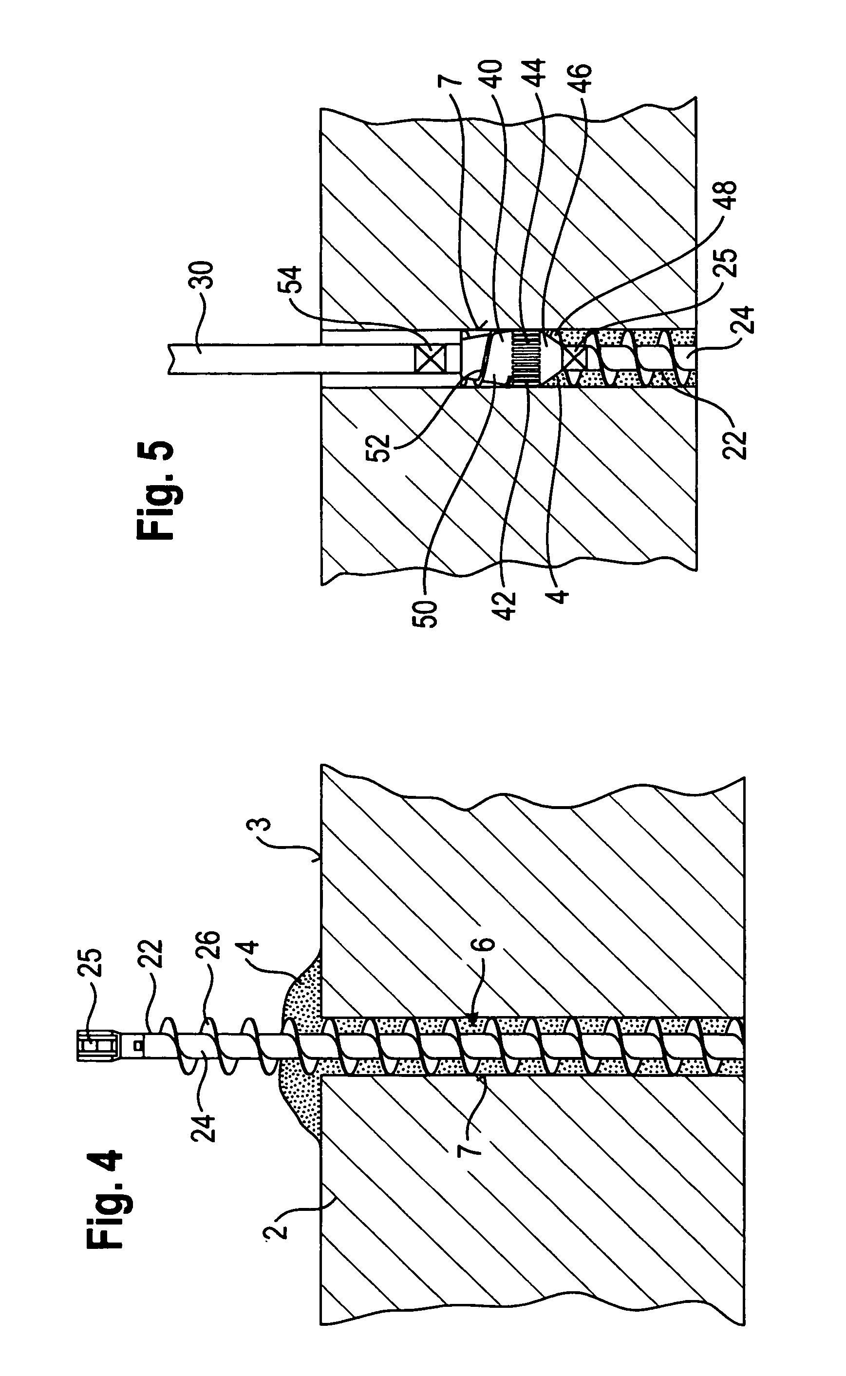
[0032]A slide 18 is mounted in known manner for displacement along the mast 12 via a cable pulley mechanism. An annular drilling drive 16 is provided on the slide 18 for the purpose of driving the bar-shaped drilling element 20. The lower region of the drilling element 20 comprises a so-called continuous screw auger 22, which is composed of a mid-conduit or core tube 24, on the outside surface of which a feed helix 26 extends over virtually the entire length thereof. A cutting unit 28 for removing the earth material is formed in known manner on the bottom end of the continuous sc...


PUM


Abstract

A drilling rig and a drilling method, in which the drilling element is caused to rotate and is displaced along a mast by means of a drilling drive, which drilling element has a continuous screw auger disposed below the drilling drive, and an extension, which is connected to the continuous screw auger and extends upwardly through the drilling drive. A displacement head is disposed between the continuous screw auger and the extension and is adapted to force earth material into the wall of a bore hole.

Description

BACKGROUND OF THE INVENTION[0001]1. Field of the Invention[0002]The present invention relates to a drilling rig comprising a mast, a drilling drive mounted for displacement thereon, and a drilling element, which can be rotatably driven and moved along the mast by the drilling drive system, the drilling element comprising a continuous screw auger disposed below the drilling drive system and an extension which is connected to the continuous screw auger and which extends upwardly through the drilling drive.[0003]The invention further relates to a drilling method, in which a drilling element is rotatably driven and moved along a mast by means of a drilling drive, the drilling element comprising a continuous screw auger disposed below the drilling drive and an extension which is connected to the continuous screw auger and which extends upwardly through the drilling drive.[0004]2. Description of Related Art Including Information Disclosed Under 37 CFR §§1.97 and 1.98[0005]The use of so-ca...

Claims


Application Information

Patent Timeline
IPC IPC(8): E21B7/00
CPCE02D5/34E21B7/005E21B7/265
Inventor STOETZER, ERWIN EMILHARTHAUSER, WERNER JOSEF
Owner BAUER MASCH GMBH
Learn More