Exhaust system hanger of vehicle
a technology of exhaust system and hanger, which is applied in the direction of machines/engines, other domestic objects, machine supports, etc., can solve the problems of not being able to appropriately deal with the large vibration, unable to absorb unable to absorb both the small vibration and the large vibration of the exhaust system, so as to achieve excellent nvh performance of the vehicle and effectively absorb the small vibration
- Summary
- Abstract
- Description
- Claims
- Application Information
AI Technical Summary
Benefits of technology
Problems solved by technology
Method used
Image
Examples
first embodiment
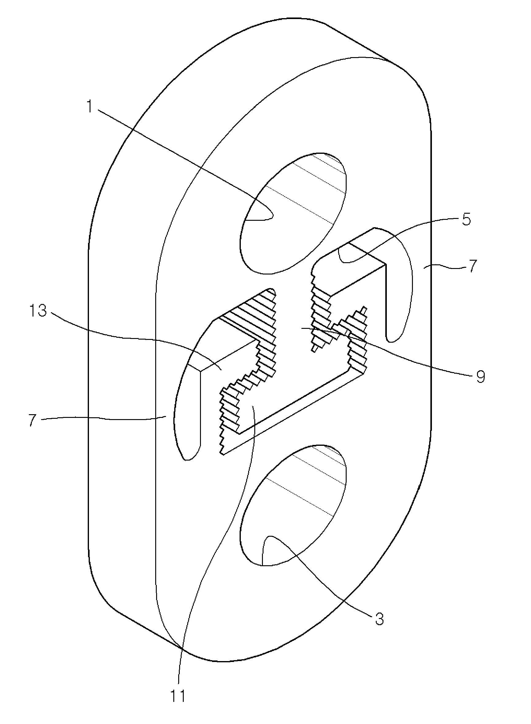
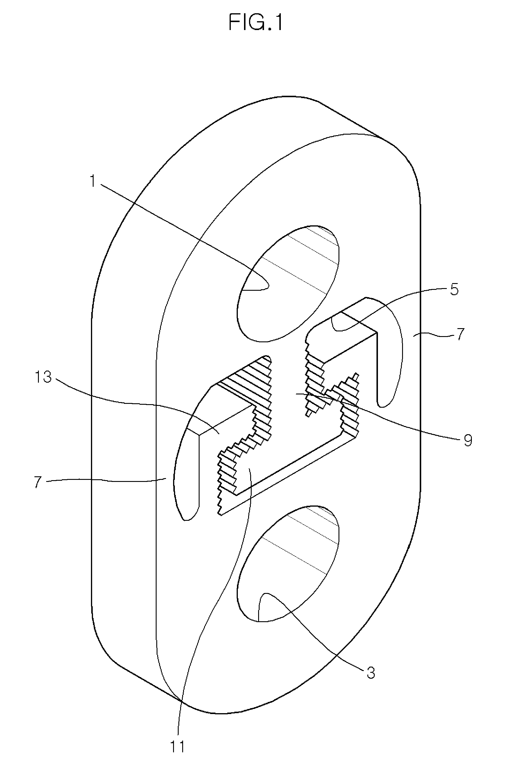
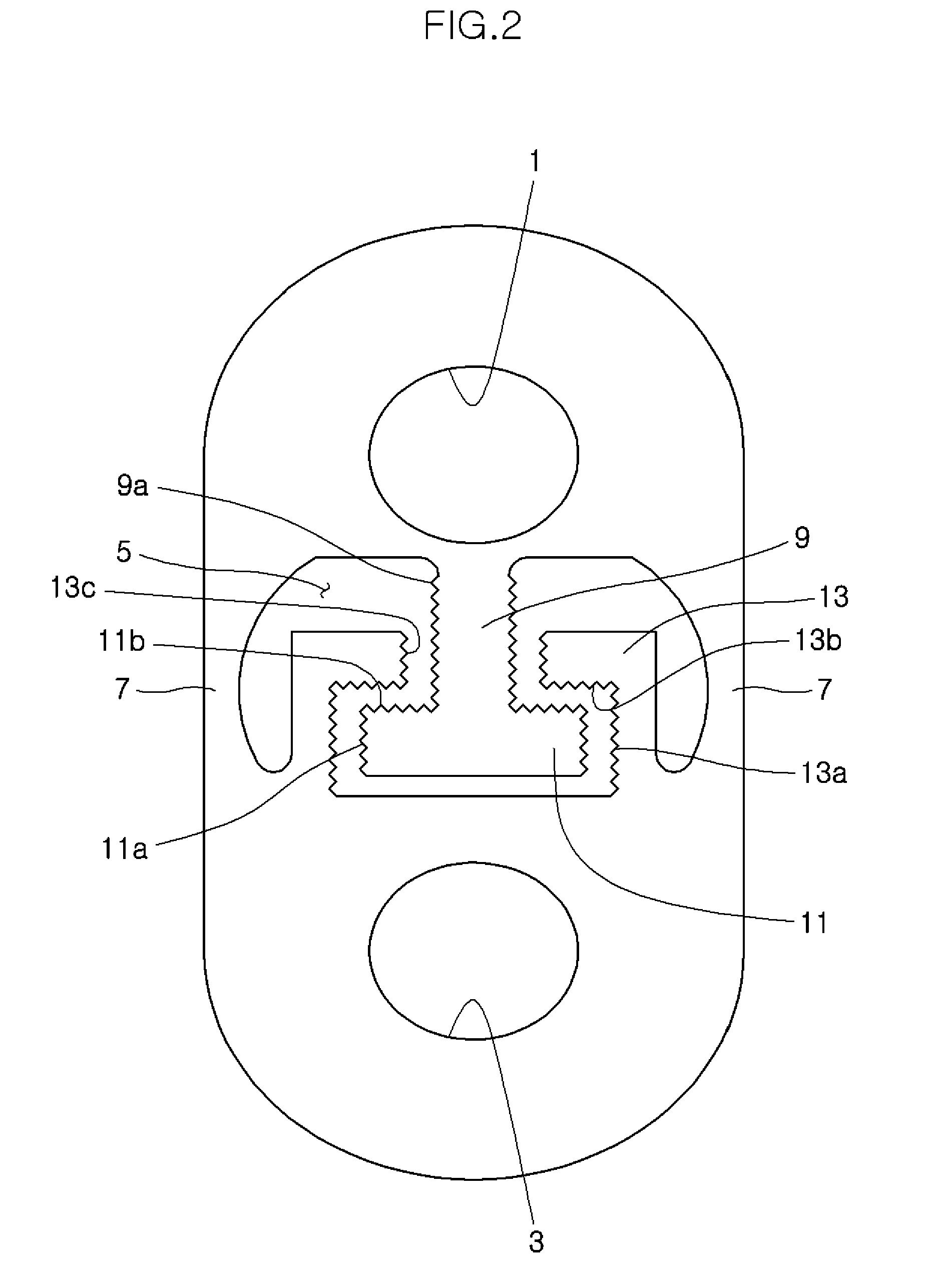
[0033]An exhaust system hanger according to the present invention is shown in FIGS. 1 and 2.
[0034]As shown in the figures, a hanger according to a first embodiment of the present invention has connection holes 1 and 3 formed at both end portions to be connected with the car body and the exhaust system, a mid-hole 5 formed between the connection holes 1 and 3, and bridges 7 with both ends connected to both sides of mid-hole 5.
[0035]A column 9 protruding from an upper surface of the mid-hole 5 toward the second connection hole 3 is formed in the mid-hole 5 and wing 11 protruding toward bridges 7 is formed at both sides of the distal end of column 9.
[0036]Further, locking portions 13 protruding from a lower surface of the mid-hole 5 toward first connection hole 1 and covering the upper surface 11b and a lateral side 11a of wing 11 is formed in mid-hole 5.
[0037]That is, column 9 and wings 11 make an inverse T-shape and locking portions 13 covering both wings 11 at their sides are formed...
second embodiment
[0053]FIG. 3 shows a hanger according to the present invention, which is different from the hanger shown in FIG. 2 in that the lateral side 11a and the upper inclined surface 11b of wing 11 are flat and the lower lateral sides 13a and the lower inclined surfaces 13b of locking portions 13 are flat in parallel with lateral side 11a and upper inclined surface 11b of wings 11, respectively. In particular, upper inclined surface 11b of wing 11 inclines toward lower inclined surfaces 13b of locking portions 13, and lower inclined surfaces 13b of locking portion 13 which face upper inclined surface 11b of wing 11 declines in parallel with upper inclined surface 11b of wing 11.
[0054]Therefore, upper inclined surface 11b of wing 11 contacts with lower inclined surfaces 13b of locking portions 13 in large vibration of the exhaust system and friction force therebetween considerably increases, such that the hanger according to the second embodiment of the present invention can effectively rest...
third embodiment
[0055]FIG. 4 shows a hanger according to the present invention, which is different from the hanger shown in FIG. 3 in that the lateral side 11a and the upper inclined surface 11b of wing 11 are indented, and the corresponding lower lateral sides 13a and the lower inclined surfaces 13b of locking portions 13 are also indented.
[0056]Further, both lateral sides 9a of column 9 are also indented and the upper lateral sides 13c of locking portions 13 which face both lateral sides 9a of column 9 are also indented.
[0057]Upper inclined surface 11b of wing 11 and lower inclined surfaces 13b of locking portion 13 incline and decline, which is the same as the hanger shown in FIG. 3.
[0058]Therefore, as in the hanger shown in FIG. 2, since both lateral sides 11a and lower lateral sides 13a are engaged and upper inclined surface 11b and lower inclined surfaces 13b are engaged while both lateral sides 9a of column 9 and upper lateral sides 13c of locking portions 13 are engaged, friction forces bet...
PUM
 Abstract
Description
Claims
Application Information
 - R&D
- Intellectual Property
- Life Sciences
- Materials
- Tech Scout
- Unparalleled Data Quality
- Higher Quality Content
- 60% Fewer Hallucinations
Browse by: Latest US Patents, China's latest patents, Technical Efficacy Thesaurus, Application Domain, Technology Topic, Popular Technical Reports.
© 2025 PatSnap. All rights reserved.Legal|Privacy policy|Modern Slavery Act Transparency Statement|Sitemap|About US| Contact US: help@patsnap.com


