
Rotary-type fluid machine

a fluid machine and rotary-type technology, which is applied in the direction of machines/engines, rotary/oscillating piston pump components, liquid fuel engines, etc., can solve the problems of vibration or noise in reduce and reduce the production cost of the rotary-type fluid machine. , the effect of reducing the vibration or noise of the rotary-type fluid machin

Inactive Publication Date: 2012-12-04
DAIKIN IND LTD
View PDF19 Cites 8 Cited by
  • Summary
  • Abstract
  • Description
  • Claims
  • Application Information

AI Technical Summary

Benefits of technology

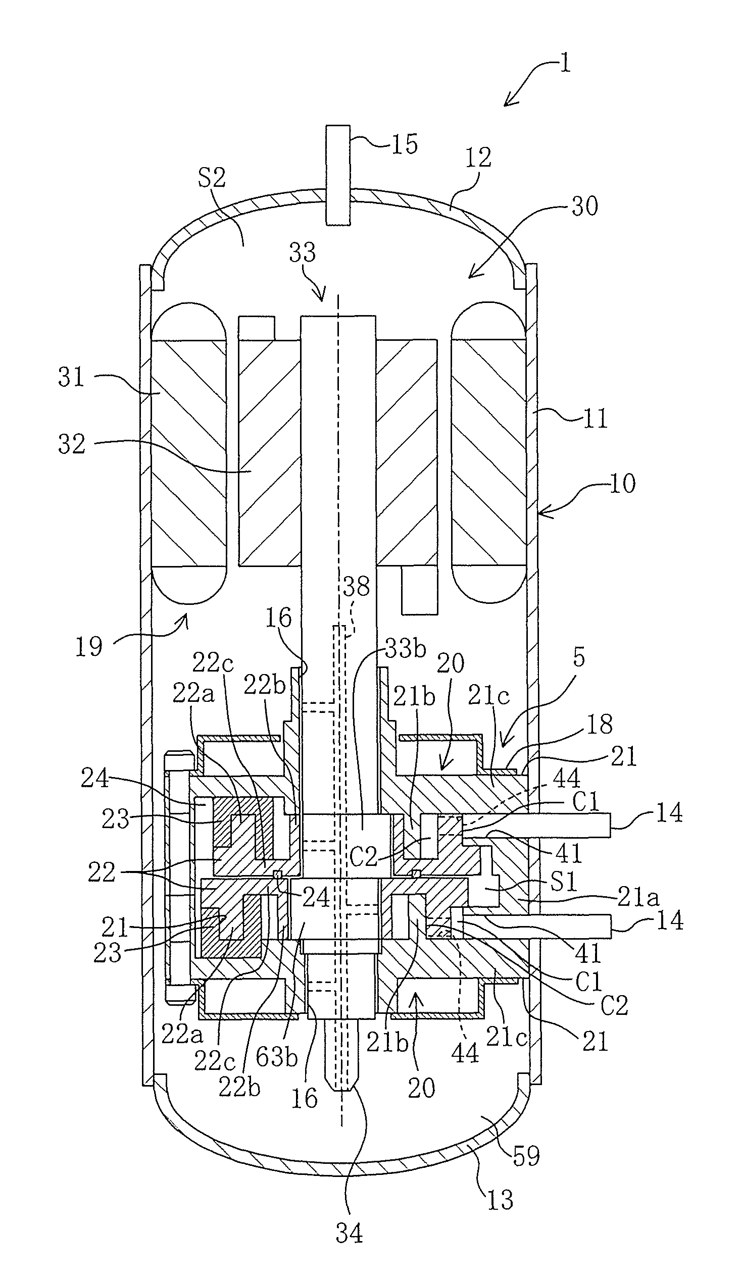
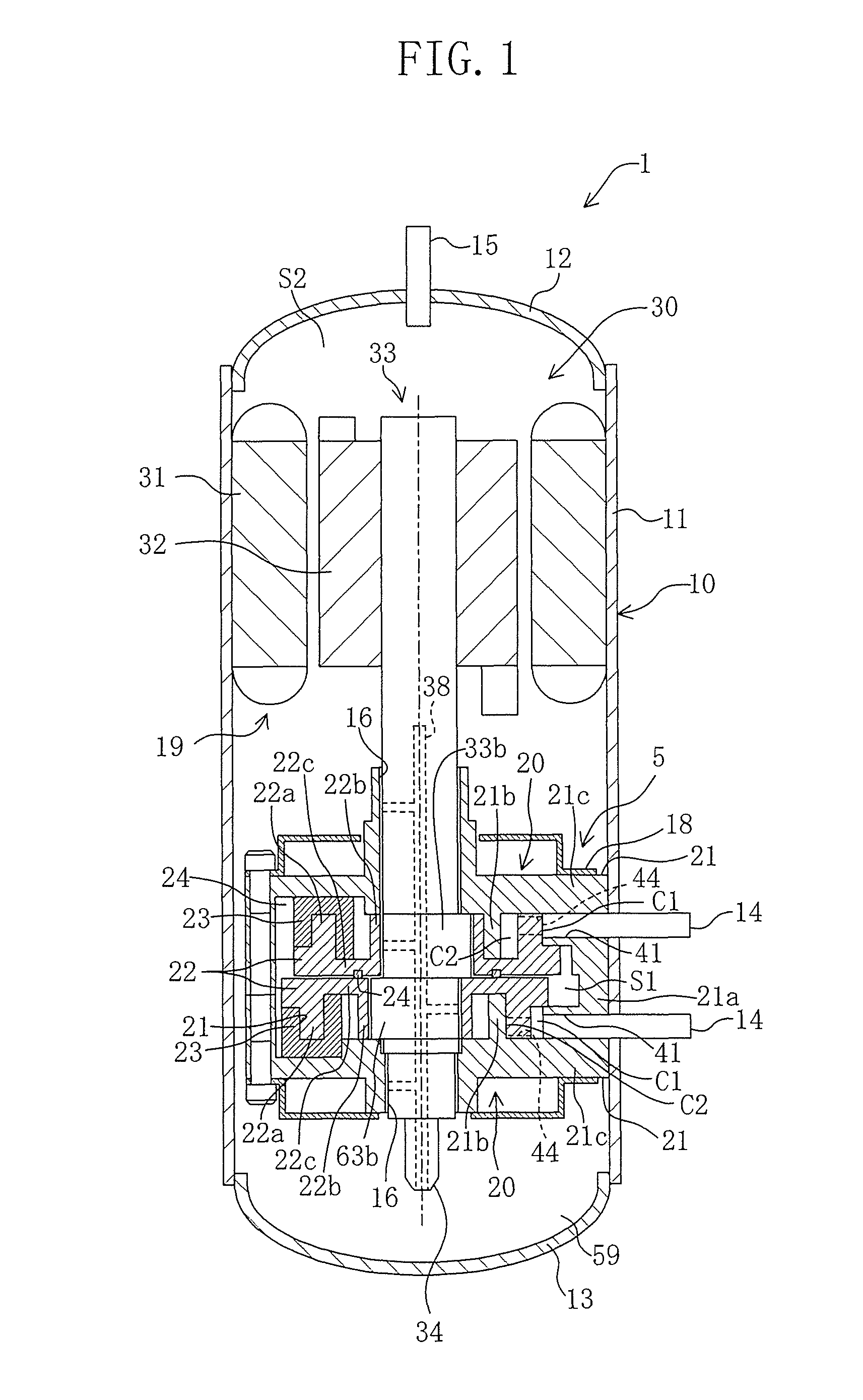
The technical problem of this patent text is to reduce the vibration and noise of a rotary compressor by suppressing the variation in output torque of the drive shaft. The solution proposed is a rotary-type fluid machine with two eccentric-rotation type piston mechanisms arranged one on top of the other, each having a cylinder and a ring-shaped piston housed eccentrically in the cylinder chamber.

Problems solved by technology

In the rotary-type fluid machine, the drive shaft rotates while undergoing a periodic variation in the output torque thereof, and the variation in the output torque may cause a vibration or a noise in the rotary-type fluid machine.

Method used


Image

  • Rotary-type fluid machine
  • Rotary-type fluid machine
  • Rotary-type fluid machine

Examples


first embodiment

Advantages of First Embodiment

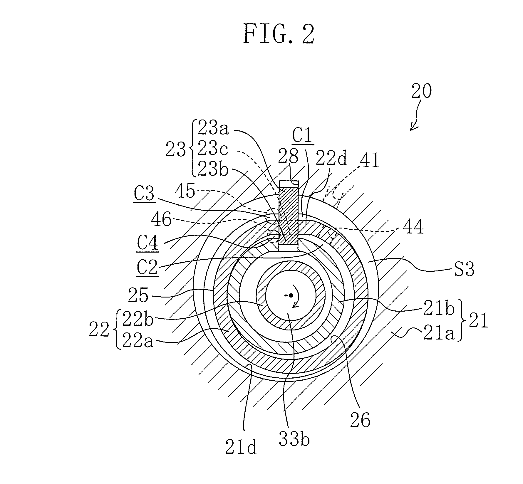
[0089]According to the first embodiment, in the ring-shaped piston (22), the outer circumferential surface (25) and the inner circumferential surface (26) of the piston portion (22a) have the same surface area. Therefore, a load exerted on the ring-shaped piston (22) (a load working on the outer circumferential surface (25)) by the gas pressure inside of the outside compression chamber (C1, C3) can be equalized to a load exerted on the ring-shaped piston (22) (a load working on the inner circumferential surface (26)) by the gas pressure inside of the inside compression chamber (C2, C4).

[0090]Here, the output torque of the drive shaft (33) is determined by the load working on the ring-shaped piston (22). Accordingly, the load working on the outer circumferential surface (25) is equalized to the load working on the inner circumferential surface (26), and thereby, the variations in the output torque of the drive shaft (33) by each compression portion (20) ...

second embodiment

Advantages of Second Embodiment

[0104]According to the second embodiment, each compression portion (100) is of a multi-vane type. Therefore, as compared with the first embodiment, a load exerted on the piston (104) (a load working on the right outer-circumferential wall surface (114)) by the gas pressure inside of the first compression chamber (101) can be easily equalized to a load exerted on the piston (104) (a load working on the left outer-circumferential wall surface (115)) by the gas pressure inside of the second compression chamber (102).

[0105]Specifically, according to the first embodiment, the ring-shaped compression chambers (C1, C2, C3, C4) are formed on the inside and outside of the piston portion (22a), and thereby, the outer circumferential surface (25) and the inner circumferential surface (26) of the piston portion (22a) each have a mutually different length in the circumferential directions. Therefore, in order to equalize the gas pressures working on the outer circu...


PUM


Abstract

A rotary-type fluid machine includes a compression mechanism having piston mechanisms arranged one on top of the other and a drive mechanism having a drive shaft that is configured and arranged to drive the piston mechanisms. Each of the two piston mechanisms includes a cylinder member with a cylinder chamber, a piston member housed eccentrically in the cylinder chamber such that the cylinder chamber is partitioned into first and second compression chambers. A phase difference of 90 degrees in volume change is made between the cylinder chambers of the two piston mechanisms. A movable one of the cylinder and piston has a first surface facing one of the first cylinder chambers and a second surface facing one of the second cylinder chambers, with a surface area of the first surface being equal to a surface area of the second surface.

Description

CROSS-REFERENCE TO RELATED APPLICATIONS[0001]This U.S. National stage application claims priority under 35 U.S.C. §119(a) to Japanese Patent Application No. 2008-013670, filed in Japan on Jan. 24, 2008, the entire contents of which are hereby incorporated herein by reference.TECHNICAL FIELD[0002]The present invention relates to a rotary-type fluid machine, and particularly to a rotary-type fluid machine including two eccentric-rotation type piston mechanisms arranged one on top of the other, the eccentric-rotation type piston mechanisms each having a cylinder formed with a cylinder chamber and a piston housed eccentrically in the cylinder chamber.BACKGROUND ART[0003]Conventionally, a rotary-type fluid machine is known which includes an eccentric-rotation type piston mechanism having a cylinder formed with a cylinder chamber and a piston housed eccentrically in the cylinder chamber. In the rotary-type fluid machine, one of the cylinder and the piston is formed as a fixed member and t...

Claims


Application Information

Patent Timeline
Patent Type & Authority Patents(United States)
IPC IPC(8): F03C2/00F04C2/00F04C18/00
CPCF04C15/0042F04C18/045F04C18/32F04C18/356F04C23/001F04C23/008F04C2250/00
Inventor SHIMIZU, TAKASHISHIBAMOTO, YOSHITAKASOTOJIMA, TAKAZOUMASUDA, MASANORI
Owner DAIKIN IND LTD
Learn More