
Combination relief valve and filtration system

Inactive Publication Date: 2012-12-04
WARR 2 BROS
View PDF13 Cites 0 Cited by
  • Summary
  • Abstract
  • Description
  • Claims
  • Application Information

AI Technical Summary

Benefits of technology

[0017]Another objective is to provide a filtration system that may be implemented and maintained without great expense, and without great investments in changes to existing systems.
[0018]A further objective is to provide a filtration system that may be easily maintained by personnel with minimal skill and expertise, but without danger of exposure of the personnel to the toxic pollutants being removed via the system.

Problems solved by technology

A known problem in the art of hydrocarbon distribution (hereby defined to include any form of transportation and storage or hydrocarbons) is that gasses can build up to unacceptably high levels within the hydrocarbon distribution system, and these gasses must be vented to relieve pressure within the system.
A well known problem with venting the gasses is the pollution caused by venting the hydrocarbons, and associated chemicals (e.g., benzene, etc.).
These types of systems are not practical for small scale releases of gas, such as this invention addresses, such as capturing vented gas from Enardo valves.
However, the prior art does not teach a combination relief valve and filtration system that enables gasses to vent from the hydrocarbon distribution system through a filter for limiting pollution released into the atmosphere.

Method used


Image

  • Combination relief valve and filtration system
  • Combination relief valve and filtration system
  • Combination relief valve and filtration system

Examples


Embodiment Construction

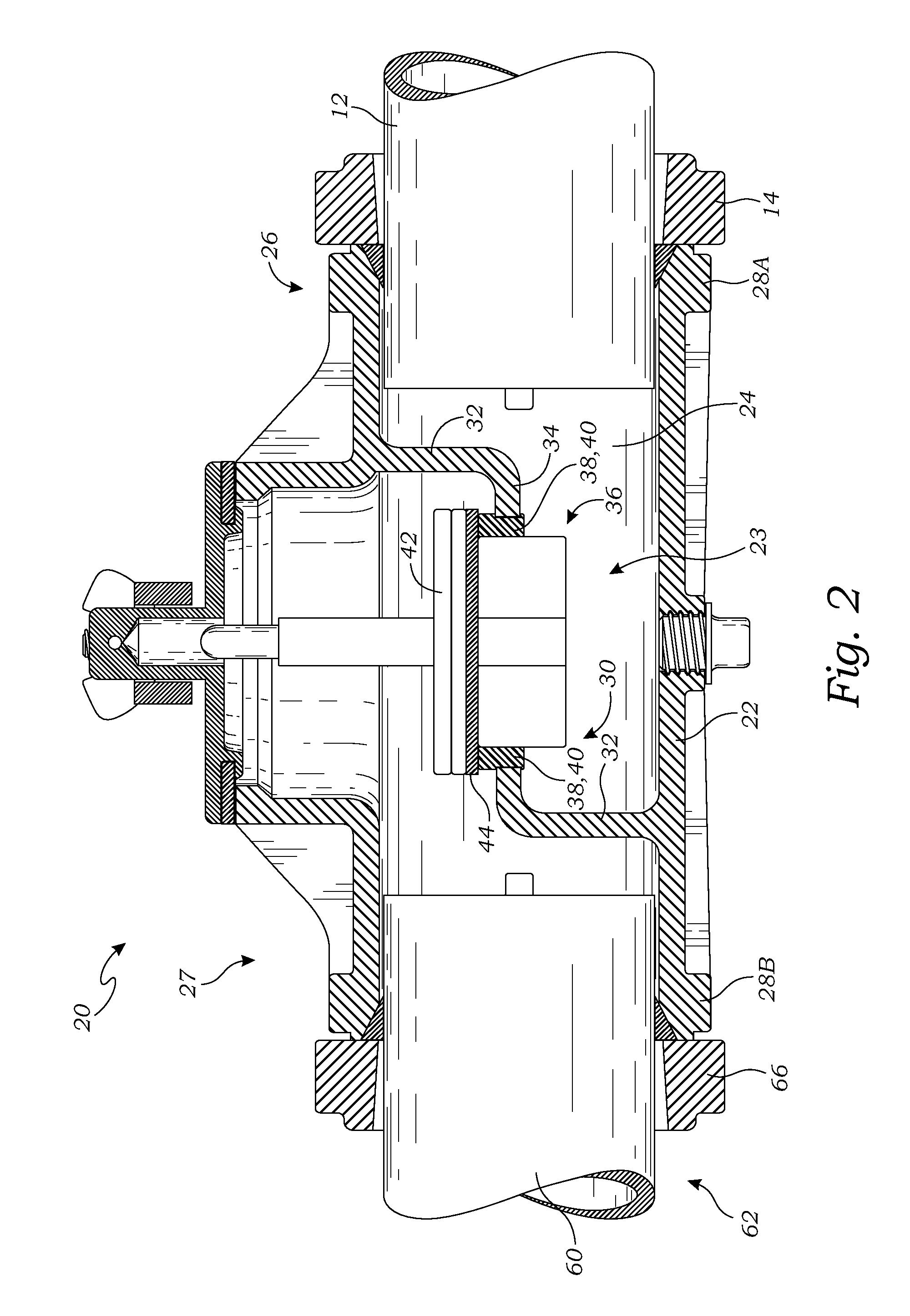
[0025]The above-described drawing figures illustrate the invention, a combination relief valve and filtration system 10 that is adapted to remove pollutants from gasses being vented from a hydrocarbon distribution system 12.

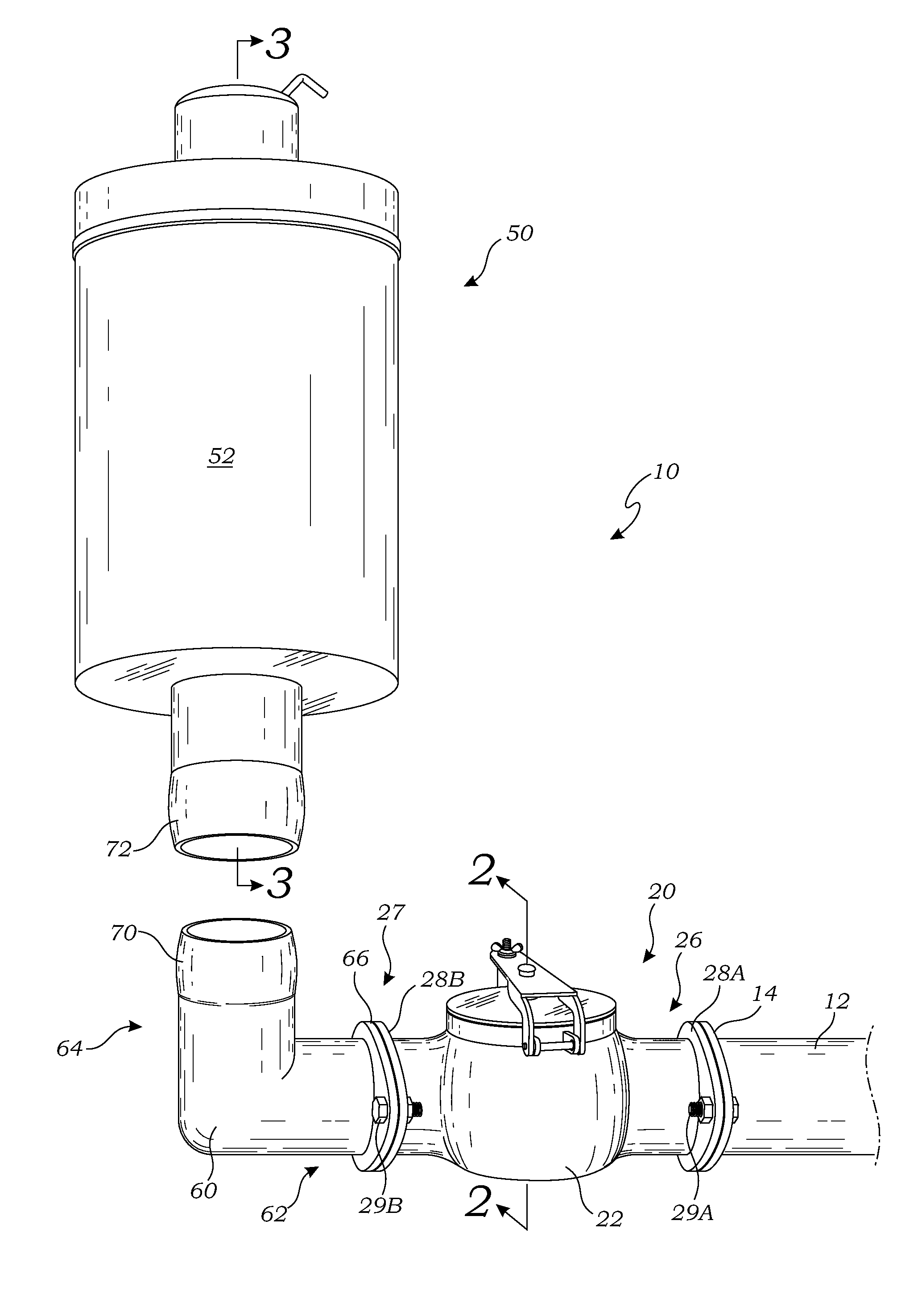
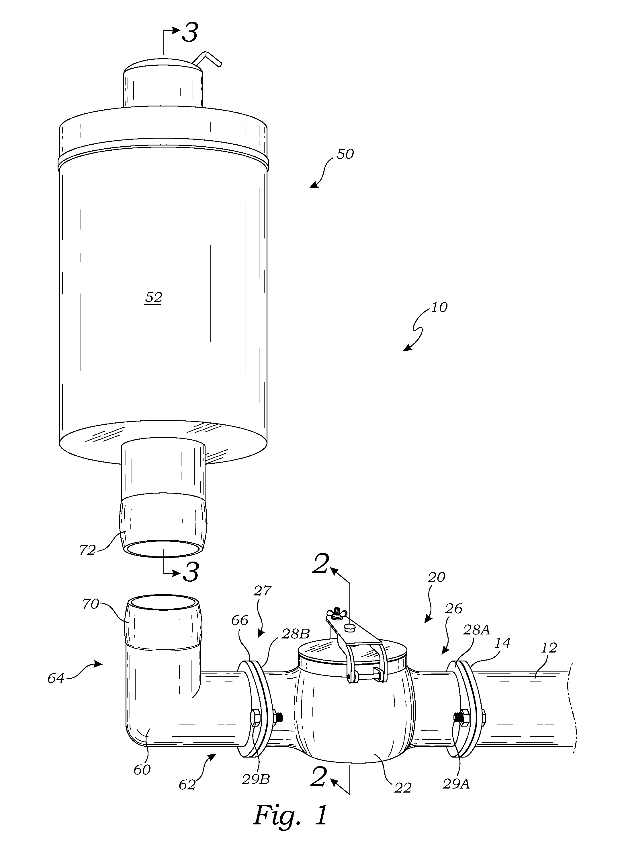
[0026]FIG. 1 is an exploded perspective view of the combination 10, according to one embodiment of the present invention. As illustrated in FIG. 1, the combination 10 includes a relief valve 20 and a filtration system 50. The relief valve 20 is operably installed on the hydrocarbon distribution system 12 for venting gasses from the hydrocarbon distribution system 12, and the filtration system 50 is mounted on a relief valve 20 for filtering pollutants from the gasses as they are vented. In this manner, venting needs are accommodated without releasing the pollutants, and without requiring a complex and expensive collection mechanism.

[0027]In the embodiment of FIG. 1, the relief valve 20 and the filtration system 50 are removably connected via a connection conduit ...


PUM


Abstract

A filtration system has a filter housing, a pollution filter, and a connection conduit. The filter housing has an inlet chamber having openings. The pollution filter is positioned within the filter housing adjacent the inlet chamber to cover the openings. The connection conduit connects the filter housing with a relief valve so that gasses vented from a hydrocarbon distribution system through the relief valve are directed into the inlet chamber and through the pollution filter, which removes pollutants from the gasses.

Description

BACKGROUND OF THE INVENTION[0001]1. Field of the Invention[0002]This invention relates generally to filtration systems, and more particularly to a combination relief valve and filtration system that enables gasses to vent from a hydrocarbon distribution system while limiting pollution released into the atmosphere.[0003]2. Description of Related Art[0004]A known problem in the art of hydrocarbon distribution (hereby defined to include any form of transportation and storage or hydrocarbons) is that gasses can build up to unacceptably high levels within the hydrocarbon distribution system, and these gasses must be vented to relieve pressure within the system.[0005]Various valves are commonly used in the art to release the gasses once pressure reaches a certain level. A vent valve (e.g., an ENARDO® valve) is commonly used for this purpose, although those skilled in the art may devise many alternative valves that are also acceptable.[0006]A well known problem with venting the gasses is t...

Claims


Application Information

Patent Timeline
IPC IPC(8): B01D53/02B01D46/00
CPCB01D53/0415B01D53/0446B01D2253/102B01D2256/24B01D2257/7027
Inventor WARREN, CHARLES
Owner WARR 2 BROS
Learn More