Electronic module for a fan of an internal combustion engine in a motor vehicle

a technology of electronic module and internal combustion engine, which is applied in the direction of machines/engines, liquid fuel engines, electric apparatus casings/cabinets/drawers, etc., to achieve the effect of disassembly and manual action of electronic modules

Inactive Publication Date: 2011-09-06
ROBERT BOSCH GMBH
View PDF9 Cites 0 Cited by
  • Summary
  • Abstract
  • Description
  • Claims
  • Application Information

AI Technical Summary

Benefits of technology

[0003]The electronic module in accordance with the invention and the fan in accordance with the invention in contrast offer the advantage that the deformable element attached to the electronic module can be engaged manually quickly and without auxiliary agents with the part of the fan serving as a mounting, thereby making time-saving assembly and any disassembly of the electronic module possible.
[0004]In comparison to mounting a deformable element on a part of the fan, preferably a fan frame being used as a mounting for the electronic module, the advantage of mounting on the electronic module is also that expenses required in the manufacturing of a fan frame for adaptation, adjustment, sampling and testing of the deformable element are eliminated and thereby both the fabrication expense as well as the tool fabrication times in the manufacturing of fan frames are clearly reduced, because the deformable element, whose production normally incurs greater expense, is integrated into the geometrically standardized component, namely into the electronic module, while the fan frame or another part of the motor vehicle being used for fastening the electronic module for engagement of the deformable element only has to be provided with a simple undercut recess or edge.
[0005]A first embodiment or the invention provides for the deformable element to have an elastically deformable snap-in projecting part of the electronic module, which is preferably embodied as a snap-in or locking hook and can engage with an undercut recess or edge on the fan frame. The function of this snap-in projecting part is that, after engaging with the undercut recess or edge of the fan frame, it restricts the freedom of movement between these two components enough so that a stable fastening of the electronic module to the fan frame that is sufficient for vehicle operation is ensured.
[0007]In order to keep the number of deformable elements required for fastening the electronic module to a minimum, another preferred embodiment of the invention also provides for at least one rigid projecting retaining element attached to the electronic module at a distance from the deformable element, which retaining element can be inserted into a receptacle or an opening of the fan frame before the deformable element engages with said fan frame and, after engagement of the deformable element, together with said element provides for fixation of the electronic module with respect to the fan frame. The retaining element can also serve to equalize tolerances and / or to limit the movement possibilities of the electronic module and can be provided with suitable geometry for this purpose.

Problems solved by technology

However, this type of assembly requires an assembly tool in the form of a screwdriver or power screwdriver as well as a certain time commitment both for assembly as well as for any disassembly that may be necessary.

Method used


Image

  • Electronic module for a fan of an internal combustion engine in a motor vehicle
  • Electronic module for a fan of an internal combustion engine in a motor vehicle
  • Electronic module for a fan of an internal combustion engine in a motor vehicle

Examples


Embodiment Construction

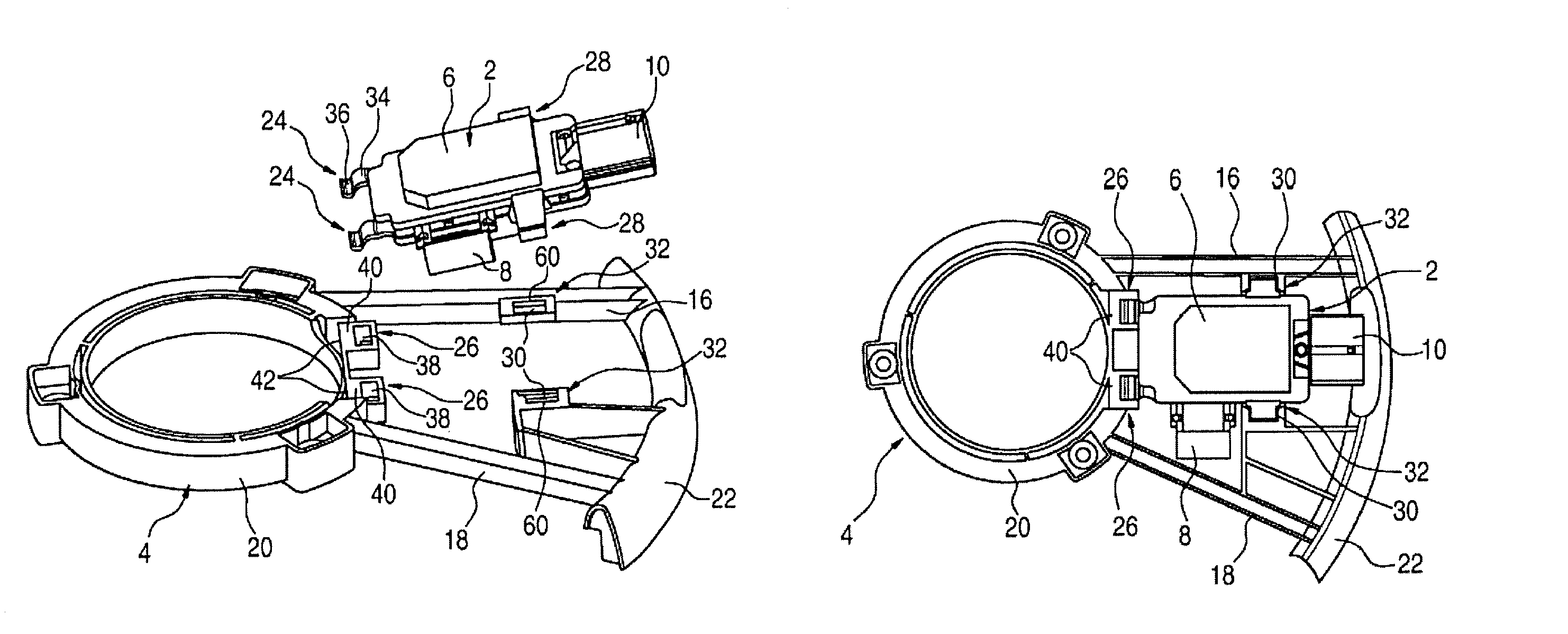
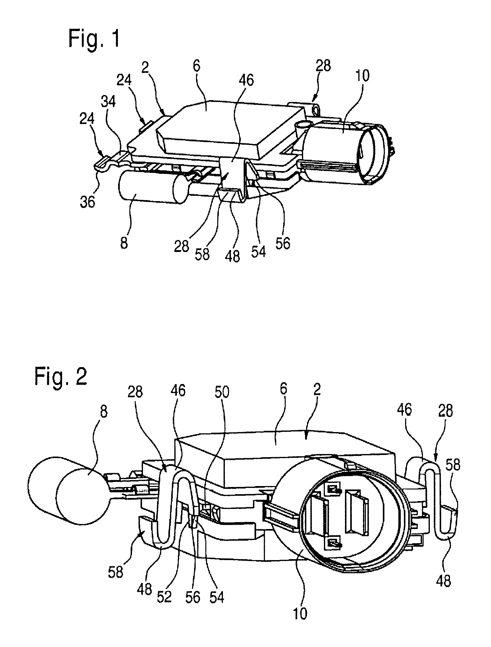
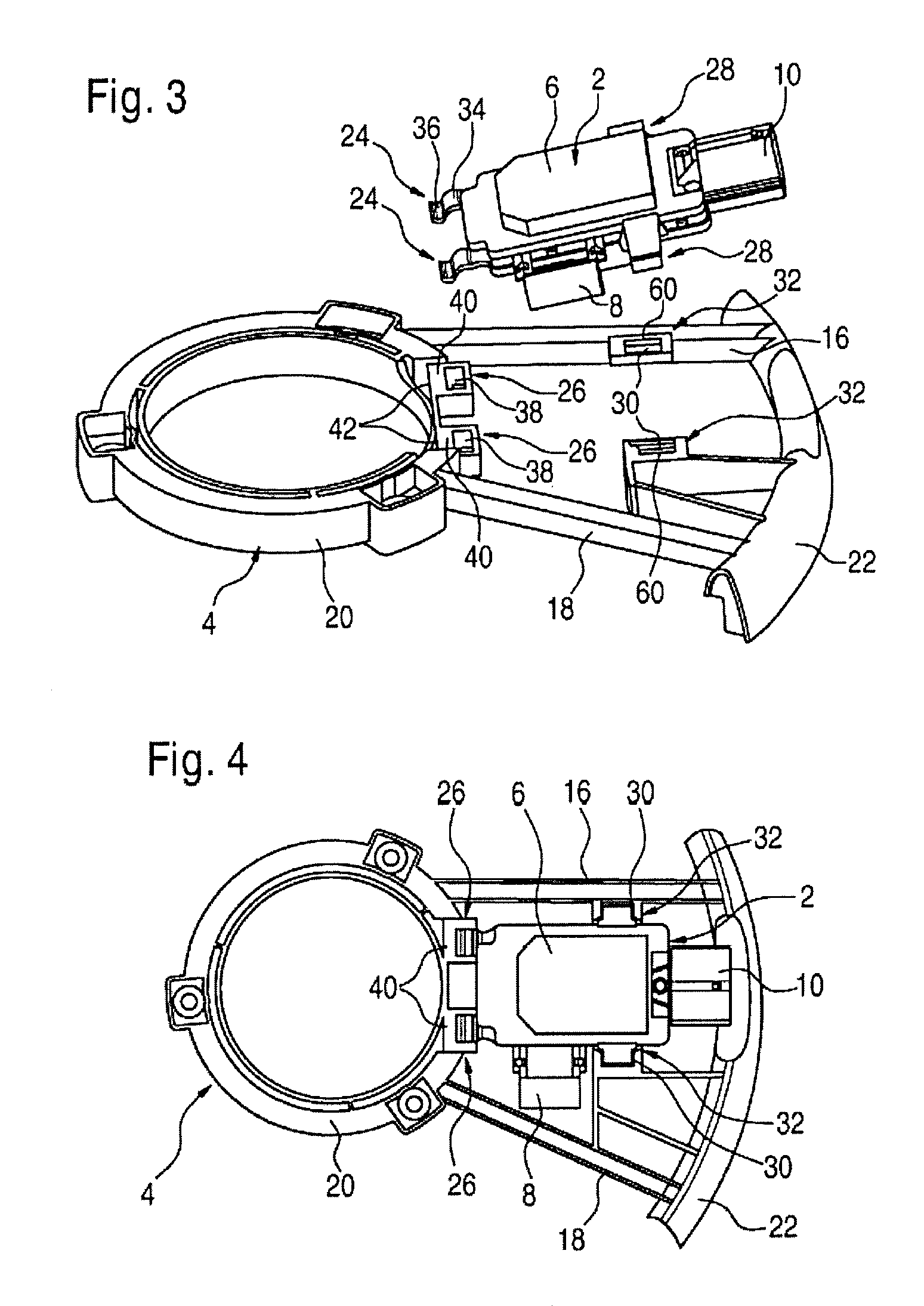
[0020]The electronic modules 2 depicted in the drawings are used to electrically or electronically control the speed and power of an electric fan drive of a cooling blower or fan being used to cool an internal combustion engine in a motor vehicle. The fan includes a frame that is depicted partially in FIGS. 3 and 4 (designated as a fan frame 4), which is used to fasten the fan in the motor vehicle and bears the fan drive and the fan wheel (not shown).

[0021]The electronic modules 2 are each comprised of a circuit board or printed circuit board or a punched grid with electronic or electrical or electromechanical components (not shown) accommodated in a housing 6, a temperature sensor 8 projecting beyond the housing 6 on a longitudinal side of said housing and, for electrical connection to the on-board power supply of the motor vehicle, are provided either with a socket 10 (FIGS. 1 through 6) for a plug cable or alternatively with a fixed plug cable 12 with a plug 14 (FIG. 12).

[0022]As...


PUM


Abstract

An electronic module for a fan of an internal combustion engine in a motor vehicle comprising at least one deformable element (12, 28, 68), which when deformed can engage with a part (4) of the fan in a detachable manner, and at least one rigid projecting retaining element (24, 66), which can be inserted in a direction of insertion into a receptacle (26) or opening (38, 78) of a fan frame (4) before the deformable element (12, 28, 68) engages, wherein after the retaining element (24, 66) is inserted into the receptacle (26) or opening (38, 78), the electronic module (2) is movable with a single degree of freedom different from the direction of insertion in order to bring the deformable element (12, 28, 68) into engagement with the fan frame.

Description

BACKGROUND OF THE INVENTION[0001]The invention relates to an electronic module for a fan of an internal combustion engine in a motor vehicle as well as a fan for cooling an internal combustion engine of a motor vehicle, with an electronic module for controlling the fan.[0002]Newer fans for cooling internal combustion engines in motor vehicles are usually equipped with an electronic module for operating and controlling the fan. In this case, it is customary to use a standardized module in the form of an add-on piece, which is suited for several types of fans with different structural designs and which is fastened to the fan after installation of the fan or after installation of said fan in the motor vehicle. The electronic module is fastened to the fan in the intake air flow on a frame of the fan that is designated as the fan frame, which is fastened on its outer circumference in the motor vehicle and bears the fan drive and the rotatably mounted fan wheel in its center, whereby most...

Claims


Application Information

Patent Timeline
Patent Type & Authority Patents(United States)
IPC IPC(8): F02B67/00
CPCF04D25/0606F04D27/00F04D29/582F01P7/048H05K5/0204H05K5/0217
Inventor EWERT, ANDREASULRICH, JENSLIEDEL, MARKUSLINNENSCHMIDT, URSULA
Owner ROBERT BOSCH GMBH
Why Eureka
Try Eureka