Chopper for a particle beam

a particle beam and chopper technology, applied in the field of choppers for particle beams, can solve the problems of chopper wheels being stressed to the limits of their mechanical strength, chopper wheels may oscillate, and choppers cannot even be operated at circumferential speed, so as to achieve the effect of more safe operation

Active Publication Date: 2012-12-04
FORSCHUNGSZENTRUM JULICH GMBH
View PDF14 Cites 3 Cited by
  • Summary
  • Abstract
  • Description
  • Claims
  • Application Information

AI Technical Summary

Benefits of technology

[0006]It is therefore an object of the invention to provide a chopper that can modulate a particle beam using a higher fr

Problems solved by technology

The disadvantage is that the material of the chopper wheels is stressed to the limits of its mechanical strength, due to centrifugal forces.
In addition, chopper wheels may os

Method used


Image

  • Chopper for a particle beam
  • Chopper for a particle beam
  • Chopper for a particle beam

Examples


Embodiment Construction

[0038]Like reference numerals in each case denote like acting elements.

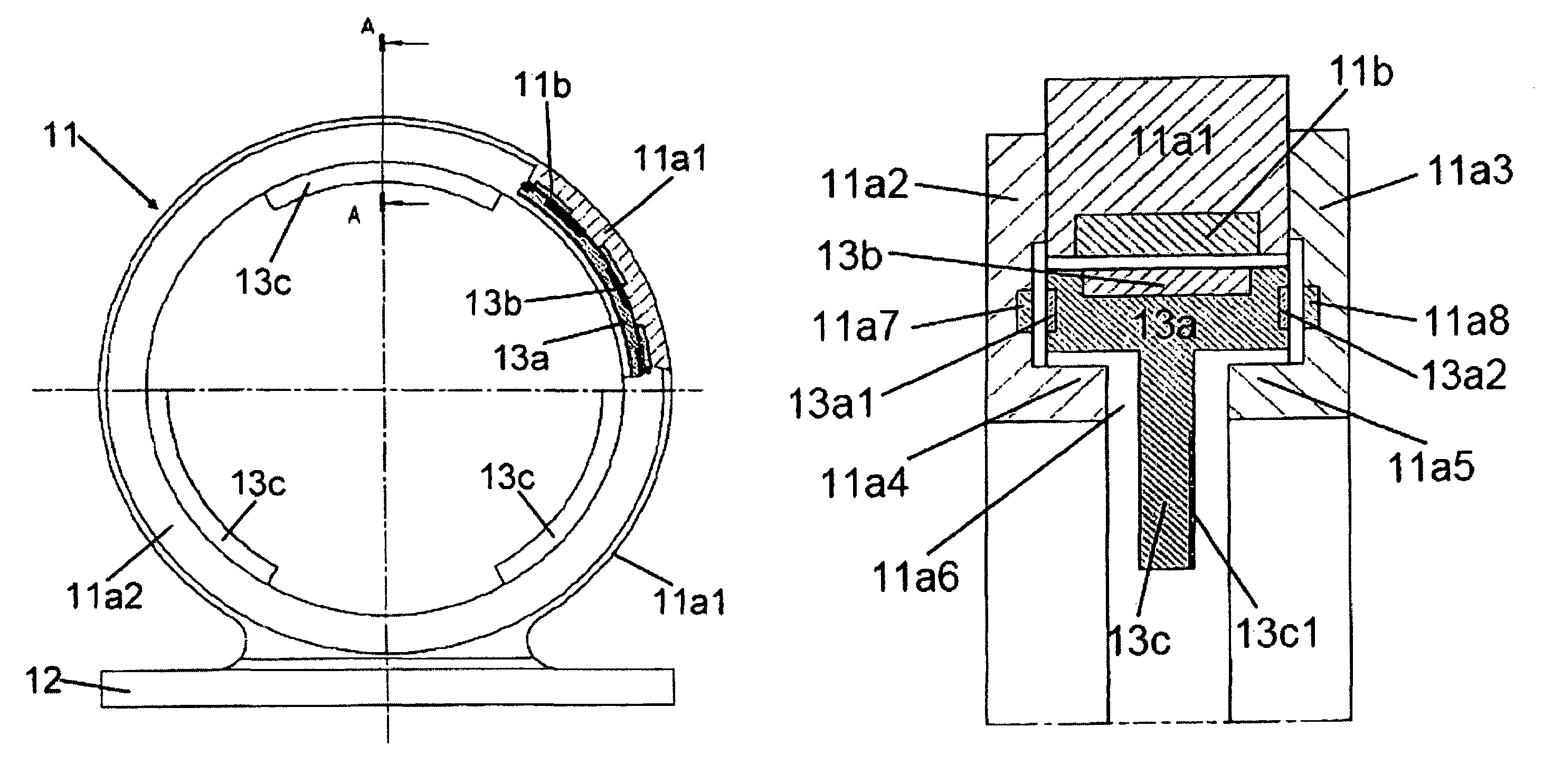
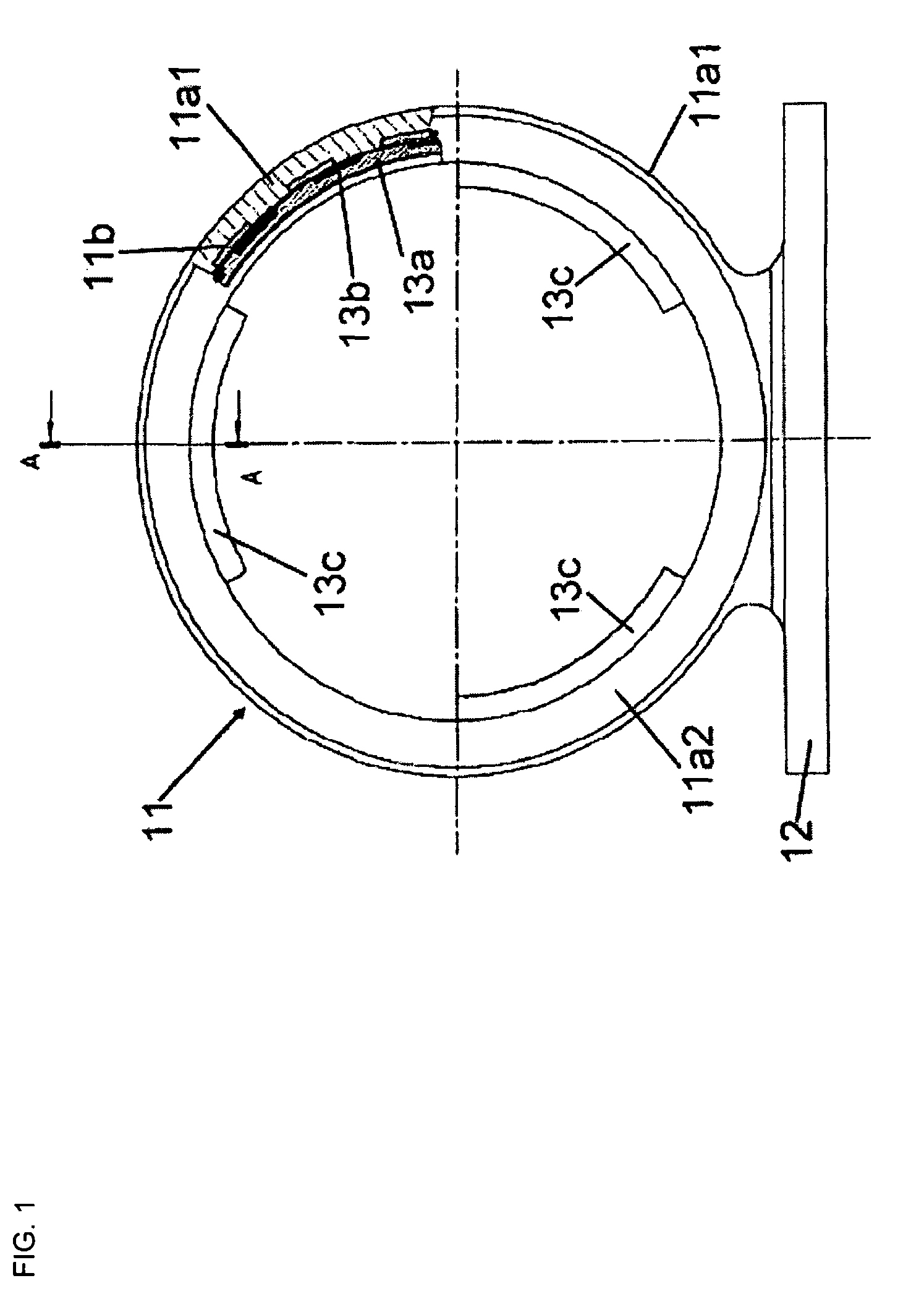
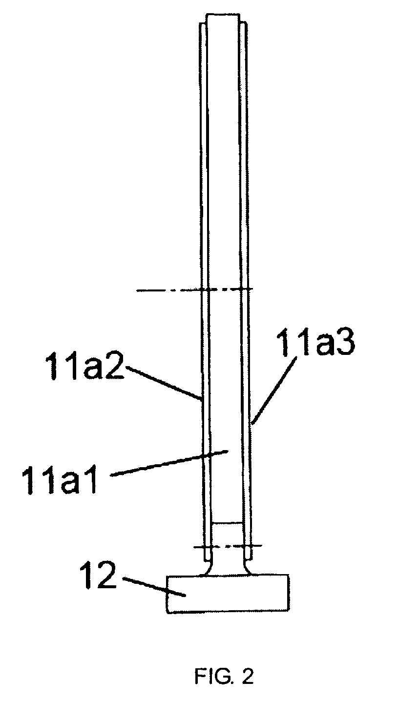
[0039]FIG. 1 shows an embodiment of a chopper according to the invention in a view along the axis of symmetry thereof (the axis of symmetry is located vertically on the drawing plane). This chopper comprises a circular ring-shaped guiding element 11 on a base 12 and a likewise circular ring-shaped control element 13 disposed concentrically with the guiding element 11. The guiding element 11 comprises a main body 11a and magnetic coils 11b. The main body 11a is composed of a circular ring 11a1, which is disposed between two circular ring disks 11a2 and 11a3. The magnetic coils 11b are sunk into the inside of the circular ring 11a1 of the main body 11a at regular intervals.

[0040]The control element 13 comprises a main ring 13a, permanent-magnetic regions 13b, and blocking regions 13c for reflecting the particle beam. The permanent-magnetic regions 13b are sunk into the outside of the main ring 13a at regular interv...


PUM


Abstract

A chopper for a particle beam comprises an annular guiding element and an element for controlling the intensity of the particle beam. The control element is supported on the guiding element so that at least one point under consideration on the control element can revolve along the circumference of the guiding element. Mounting along a circumference allows for accommodation of considerably higher disturbance torque than mounting on a rotational axle, using the same bearing force. Furthermore, it is possible to dispense with the entire rotational axle, and the control element can be designed, for example, as a ring. This brings about considerable weight savings as compared to chopper wheels according to the prior art, which accordingly enables higher circumferential speeds and therefore higher modulation frequencies for the particle beam, while at the same time increasing operational safety.

Description

[0001]The invention relates to a chopper for a particle beam.BACKGROUND OF THE INVENTION[0002]Choppers are used to divide a continuous particle beam into spatially and temporally delimited pulses. A chopper is an element which comprises both regions that allow the particle beam to pass and regions that block the particle beam. As the chopper is moved through the particle beam, the open and blocked regions pass alternatingly through the particle beam, thereby modulating the particle beam.[0003]Choppers configured as wheels, which are rotated through the particle beam, are known from DE 10 2004 002 326 A1. An essential aspect of the performance of such a chopper is the maximum frequency with which it can modulate the particle beam. This frequency is determined by the circumferential speed at the edge of the chopper wheel, which in turn is defined by the diameter and the rotational speed.[0004]The aforementioned published prior art discloses that circumferential speeds of approximately...

Claims


Application Information

Patent Timeline
IPC IPC(8): H01J1/46
CPCG21K1/043G21K1/04
Inventor RENFTLE, WALTERKAEMMERLING, HANSPRAGER, MICHAELPRAGER, LEGAL REPRESENTATIVE, MAGDALENA
Owner FORSCHUNGSZENTRUM JULICH GMBH
Why Eureka
Try Eureka