Communication apparatus, communication method, and integrated circuit

a communication apparatus and integrated circuit technology, applied in the field of communication apparatus, communication method, communication system, can solve the problem of increasing the bit error of reception data, and achieve the effect of reducing the transmission efficiency caused by the redundancy of the pilot symbol and reducing the transmission efficiency

Active Publication Date: 2012-12-04
PANASONIC CORP
View PDF17 Cites 5 Cited by
  • Summary
  • Abstract
  • Description
  • Claims
  • Application Information

AI Technical Summary

Benefits of technology

[0010]The embodiment described later is devised in view of such a circumstance and an object is to provide a communication apparatus, a communication method, and an integrated circuit capable of avoiding reduction of transmission efficiency caused due to variation in a state of a transmission channel.
[0012]According to the communication apparatus having the above-described configuration, the inserting of the pilot symbol in the communication frame is controlled on the basis of the state of the transmission channel. Therefore, since it is possible to appropriately insert the pilot symbol in the communication frame, reduction of transmission efficiency caused due to redundancy of the pilot symbol can be avoided.
[0014]In the communication method according to the first aspect of the invention, the inserting of the pilot symbol in the communication frame is controlled on the basis of the state of the transmission channel. Therefore, since it is possible to appropriately insert the pilot symbol in the communication frame, the reduction of the transmission efficiency caused due to the redundancy of the pilot symbol can be reduced.
[0016]In the integrated circuit having the above-described configuration, the inserting of the pilot symbol in the communication frame is controlled. Therefore, since it is possible to appropriately insert the pilot symbol in the communication frame, the reduction of the transmission efficiency caused due to the redundancy of the pilot symbol can be reduced.
[0017]As apparent from the above-described invention, the communication apparatus, the communication method, and the integrated circuit are capable of reducing transmission efficiency while avoiding inserting a redundant pilot symbol.

Problems solved by technology

When impulse noise or phase fluctuation occurs in a transmission channel such as communication using a power line or mobile wireless communication or when the amplitude or phase of a reception signal varies due to fading or the like, distortion may occur in the reception signal, thereby increasing a bit error of reception data.

Method used


Image

  • Communication apparatus, communication method, and integrated circuit
  • Communication apparatus, communication method, and integrated circuit
  • Communication apparatus, communication method, and integrated circuit

Examples


Embodiment Construction

[0032]Hereinafter, an exemplary embodiment of the invention will be described with reference to the drawings.

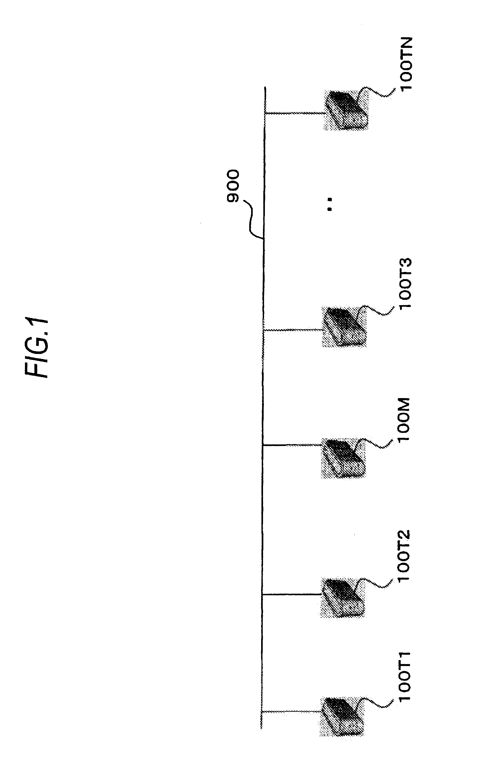
[0033]As shown in FIG. 1, a power line communication system includes a plurality of PLC (Power Line Communication) modems 100M, 100T1, 100T2, 100T3, and 100T4 connected to a power line 900. In the power line communication system shown in FIG. 1, five PLC modems are illustrated, but arbitrary number of the PLC modems is used. The PLC modem 100M functions as a master modem and manages a connection state (link state) of the other PLC modems 100T1 to 100T4 each functioning as a slave modem. However, the PLC modem functioning as the master modem is not always needed.

[0034]In the following description, terms of the PLC modems 100M, 100T1, 100T2, 100T3, and 100T4 are used when the master modem and the specific slave modems are mentioned, and a term of the PLC modems 100T is used when the slave modems are mentioned on the whole. In addition, a term of the PLC modems 100 is used when ...


PUM


Abstract

A communication apparatus is connected to a transmission channel for transmitting data to another communication apparatus. The communication apparatus includes: a communication frame generator which generates a communication frame for storing the data; and a controller which controls to insert a pilot symbol into the communication frame based on a state of the transmission channel.

Description

BACKGROUND[0001]1. Technical Field[0002]The present invention relates to a communication apparatus, a communication method, and a communication system capable of carrying out communication using communication parameters suitable to states of a transmission channel.[0003]2. Background Art[0004]When impulse noise or phase fluctuation occurs in a transmission channel such as communication using a power line or mobile wireless communication or when the amplitude or phase of a reception signal varies due to fading or the like, distortion may occur in the reception signal, thereby increasing a bit error of reception data.[0005]As a method of solving such a problem, a method of inserting a pilot symbol into a reception signal is disclosed in Patent Document 1 (JP-A-2002-84332) and Patent Document 2 (JP-A-2006-352492), for example. The pilot symbol is a known signal. Generally, the plural pilot symbols are inserted at periodic interval. Accordingly, since a characteristic of a transmission ...

Claims


Application Information

Patent Timeline
Patent Type & Authority Patents(United States)
IPC IPC(8): H04B1/00
CPCH04L1/0001H04L5/0048H04L5/006H04L27/2613H04B2203/5495H04L1/12H04L5/0007H04B2203/5408H04B2203/5445H04B2203/5454H04L27/26134
Inventor KONISHI, TAISUKENOMA, NOBUHIKOKODAMA, NOBUTAKAKOGA, HISAOYOSHIDA, SHIGEO
Owner PANASONIC CORP
Why Eureka
Try Eureka