Positive airway pressure system with head position control

a positive airway pressure and head position technology, applied in mechanical equipment, valves, operating means/releasing devices, etc., can solve the problems of blood oxygen drop, restorative sleep, blood carbon dioxide rise, etc., to improve patient comfort, reduce gas pressure, and less noise

Active Publication Date: 2012-12-11
RESMED INC
View PDF40 Cites 37 Cited by
  • Summary
  • Abstract
  • Description
  • Claims
  • Application Information

AI Technical Summary

Benefits of technology

[0030]During sleep, the position of the patient's head can be the most important determinant of critical pressure for the patient since the anatomical structures that might block the airway (such as the tongue, the soft palate, the uvula and the tonsils) are in the head. Thus, the position sensor that determines the position of the head can be valuable in effectively controlling the pressure output of a PAP system.
[0035]The features of this invention would allow a PAP system to provide different suitable gas pressures depending on the head position of the patient. This would improve patient comfort while providing the critical pressure at different positions to maintain an open airway. Additionally, since patients prefer lower PAP pressures, such a system might also cause patients to prefer to sleep in positions (such as a lateral position) that cause the system to provide a lower gas pressure to the patient. The lower output pressure would also spur the patient to sleep in a position that leads to fewer airway blockages. The lower output pressure would tend to disturb a person's sleep much less because of comfort of lower pressure and less noise due to the slower operation of the compressor drive motor.
[0036]A wearable PAP system embodying features of the invention preferably has one or more housings which insulate the patient's head from heat, sound and vibration from the from the PAP system. For example a pad may be positioned at the bottom of the housing(s) or the bottom of the housing may be spaced from the patient's head to minimize such heat, noise and vibrations. The drive motor for the compressor may have additional vibration and noise dampers to produce a less disturbing operation. Materials such as foams, gels, plastic members, rubber-like members or contained fluids may be used to isolate and / or reduce the noise and vibrations which emanate from the pressure source.
[0037]Further, a PAP system embodying features of the invention may be spaced from the top of the patient head and be supported by pod extensions or feet which are secured to the harness assembly. The bottoms of the pod extensions or feet are preferably padded to minimize patient discomfort. Because a substantial portion of the bottom surface of the housing is spaced away from the patient's head, trapped heat underneath the bottom of the housing is minimized. The open space between the patient's head and the bottom of the housing(s), in addition to providing ventilation also reduces noise and vibration from the system housing to the patient.
[0038]Moreover, because a self-contained PAP system embodying features of the present invention does not have a gas delivery tube connecting the patient's face mask to a remote pressure generating unit, there are fewer restrictions on a patient's movement during sleep. There is little or no likelihood of pulling the mask away from its operative position on the patient's face, and there is no remote pressure generating unit which might be pulled off an adjacent night stand.

Problems solved by technology

This will cause a drop in blood oxygen and a rise in blood carbon dioxide.
OSA disrupts restorative sleep.
The limited success of these approaches likely stems from the fact that they don't address all anatomical sources of a blockage.
The drawback to a CPAP system is poor patient compliance, i.e. continuous use by the patient.
But, as higher pressure makes the CPAP system more uncomfortable to the patient, patient compliance drops.

Method used


Image

  • Positive airway pressure system with head position control
  • Positive airway pressure system with head position control
  • Positive airway pressure system with head position control

Examples


Embodiment Construction

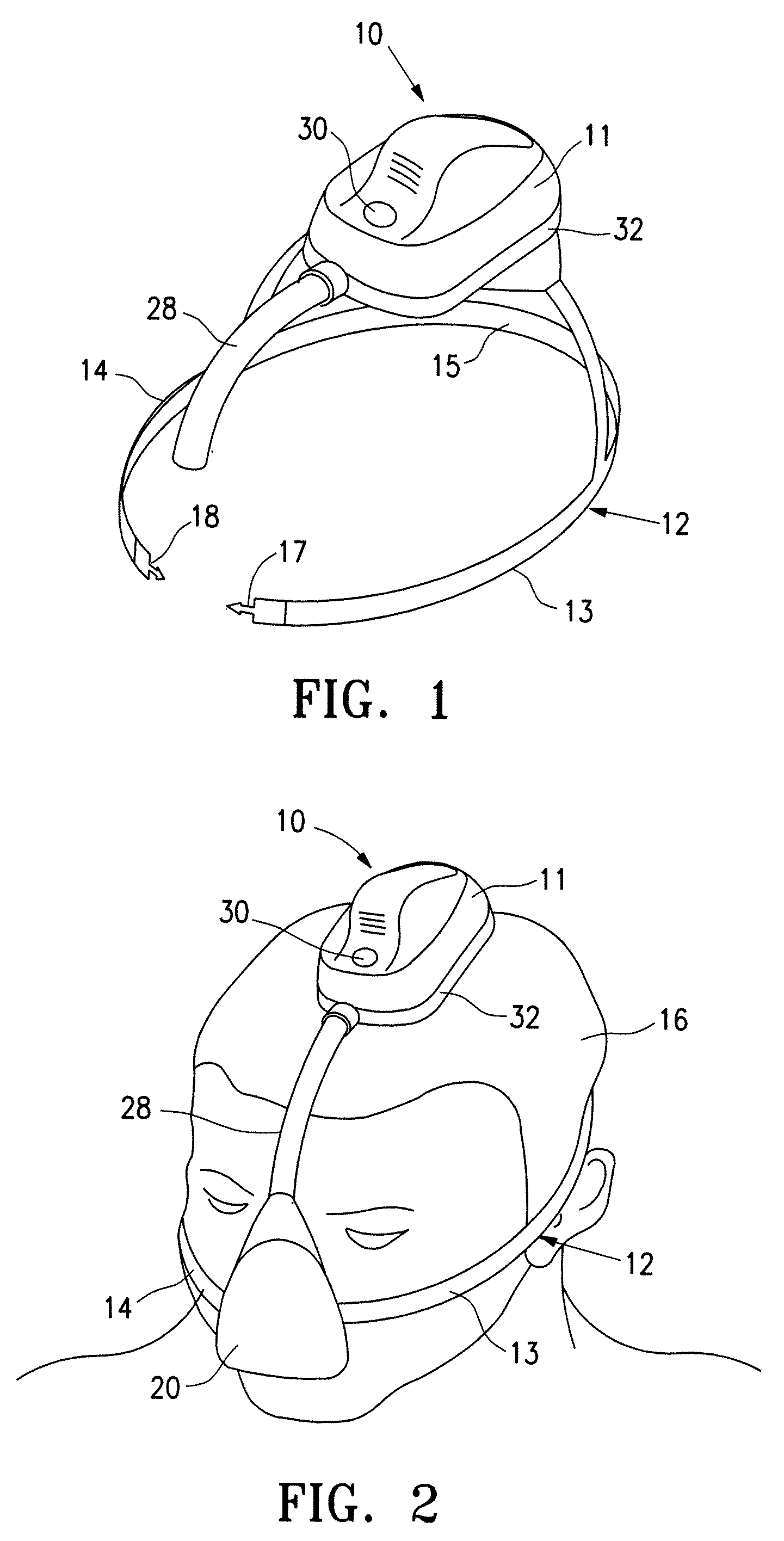
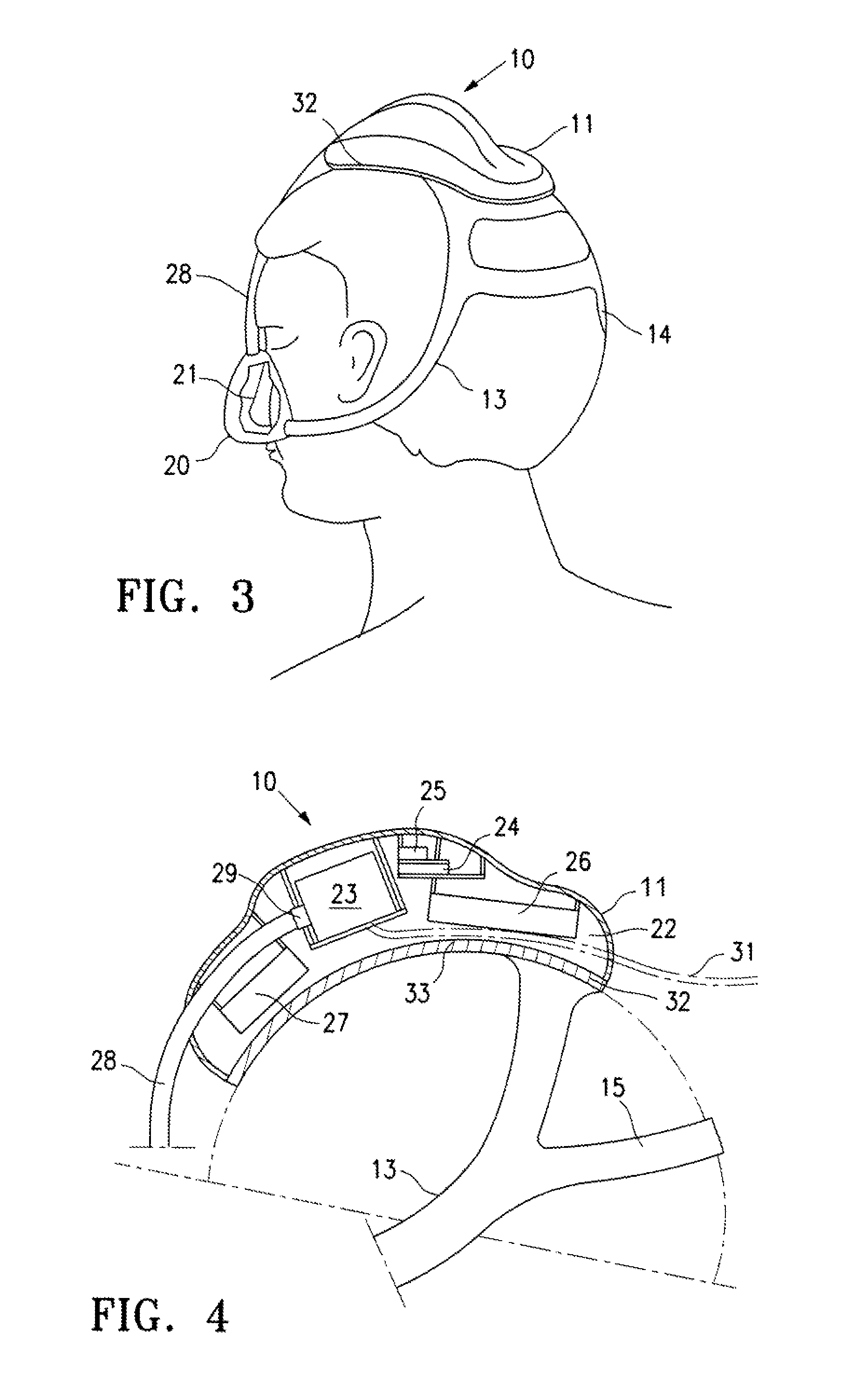
[0064]FIGS. 1-3 are perspective views of a PAP system 10 embodying features of the invention. As shown, the system 10 basically includes a system housing 11 and a harness assembly 12 secured to the bottom of the housing. The harness assembly 12 has a plurality of straps 13 and 14 and cross strap 15 to secure the housing 11 to a patient's head 16 as shown in FIG. 2. The free ends of straps 13 and 14 have push in type connectors 17 and 18, as shown in FIG. 1, for securing the free ends to mask 20 as shown in FIG. 2. The straps 13-15 hold the mask 20, as shown in FIG. 2, in a sealed engagement with the patient's nose 21.

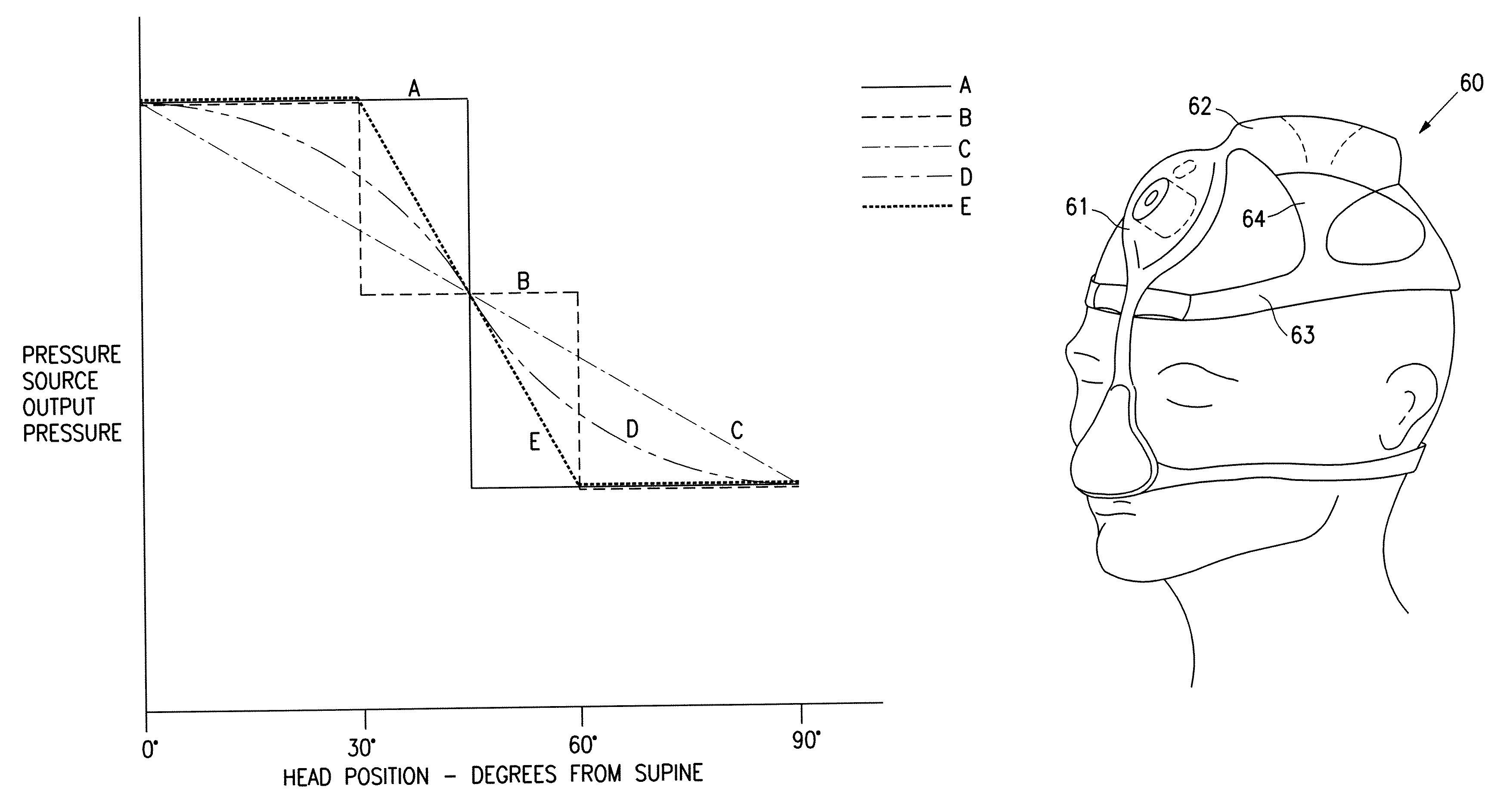
[0065]As best shown in FIGS. 4 and 5, the interior 22 of system housing 11 contains a compressor 23, a controller 24, a position sensor 25 and batteries 26 and 27 to supply electrical power to the compressor 23. A gas delivery tube 28 is secured to the discharge 29 of the compressor 23 and extends to the mask 20 for the delivery of a breathable gas to the patient's nose...


PUM


Abstract

The invention is directed to a positive airway pressure (PAP) system with a head mounted harness assembly with a housing and a head position sensor located within or secured to the housing that detects the position of a patient's head, and communicates this head position information to a controller of the system which may be disposed within the housing having the position sensor or a second housing. The controller varies the output pressure of the pressure source, e.g. a rotary compressor, based, at least in part, on the head position information provided by the head position sensor. In a preferred embodiment, the position sensor is an accelerometer.

Description

RELATED APPLICATIONS[0001]This application is related to and claims priority from provisional application Ser. No. 61 / 440,685, filed on Feb. 8, 2011, which is incorporated herein by reference in its entirety.FIELD OF THE INVENTION[0002]The invention is generally directed to a system and method for controlling the treatment a patient receives and particularly to controlling a Positive Airway Pressure (PAP) device.BACKGROUND OF THE INVENTION[0003]During sleep, all muscles, including those of the upper airway, lose tone and relax. Obstructive Sleep Apnea (OSA) occurs when tissue blocks the upper airway during sleep. This will cause a drop in blood oxygen and a rise in blood carbon dioxide. The brain will sense these changes, and awaken the person enough to restore muscle tone to the structures of the upper airway, and the airway will reopen.[0004]The severity of OSA is determined by the number of blockages per hour of sleep, also called the apnea-hypopnea index (AHI). These include com...

Claims


Application Information

Patent Timeline
Patent Type & Authority Patents(United States)
IPC IPC(8): A61M16/00
CPCA61M16/0057A61M16/00A61M16/0069A61M16/0051A61M16/0683A61M16/0875A61M2210/06A61M2230/62A61M2230/63A61M2209/088A61M2205/8206A61M2205/8262A61M2205/70A61M2205/332A61M2205/3355A61M2205/8218A61M2230/005A61M16/204A61M16/0003A61M16/0616A61M16/202A61M2016/0027A61M2205/3303A61M2205/3331A61M2205/42A61M2205/52A61M16/024
Inventor BOWDITCH, NATHANIEL L.GOFF, THOMAS G.CASEBOLT, TARMIGAN
Owner RESMED INC
Why Eureka
Try Eureka