Hose

a technology of hoses and hoses, applied in the direction of hose connections, other domestic objects, mechanical apparatus, etc., can solve the problems of fabric liner splitting, large stress applied to the hose at the pinch point of the coupling, and increase the demands of pumping equipment, etc., to achieve long distance transport of fluids and high pressure

Inactive Publication Date: 2012-12-11
ALL AMERICAN HOSE ACQUISITIONS LLC
View PDF39 Cites 7 Cited by
  • Summary
  • Abstract
  • Description
  • Claims
  • Application Information

AI Technical Summary

Benefits of technology

[0015]The tailpiece of the invention includes a wave form (sinusoidal or other waveform) which prevents pinch points. Current couplings, for instance those which meet the “mil spec”, create sharp edges causing tears and the like in the liners of the hose and in the fabric which supports those liners. “Mil spec” stands for military specification. Pinch points are also created in the prior art devices between various clamping components. Pinch points prevent the hose from stretching any allowable amount thus causing excessive tension in specific areas of the hose causing the fabric liner to split. The wave form used in the invention applies a constant force across the hose, thus reducing the stress on the fabric liner. The sleeve includes interlacing reciprocal fingers (interdigitated fingers) which prevent a straight line pinch point on the hose when the sleeves are clamped together and retained by the collars. A straight line pinch point can cause a leak path for fluid to egress. The latch assembly is made up of a pivot bar, bolts and washers. Bolts are partially threaded into the pivot bar which is placed in a retaining groove on one collar then swung into place on the other collar. Clamping can also be accomplished by threading the bolts directly into one of the collar halves. The function of the gasket is to prevent fluid egress into the coupling.
[0020]An inner liner includes an exterior coated with adhesive and the inner liner engages the outer warp fibers, weft fibers and pillars of the outer jacket. The example of the hose disclosed herein has been tested to a pressure of 2250 pounds per square inch without bursting. Similarly, the hose coupling disclosed herein has been tested to a pressure of 2250 pounds per square inch without the extraction of the hose. A process for making the hose, comprises the steps of: forming an inner liner and coating the exterior thereof with adhesive; weaving, in a twill weave pattern, Vectran® yarn, in a repeating 2-4-2-4-2 pattern in both the warp and the weft directions; extruding polyurethane onto the woven vectran yarn, some of the polyurethane extending into pillars between the warp and weft yarn, forming an outer liner; inserting the inner liner coated with adhesive within the outer liner; and, pressurizing the inner liner with steam expanding the inner liner and the adhesive into engagement with the vectran yarn and polyurethane pillars of the outer liner. The 2-4-2-4 repeating pattern of the woven yarns forms small angles over and under the respective warp and weft yarns and the strength of the hose is enhanced using this pattern. Other warp and weft yarn patterns may be used and are specifically contemplated. The woven vectran yarn outer jacket is pulled over the mandrel under tension and the tension is low enough so as to not damage the Vectran® yarn. The tension is low because the polyurethane application is primarily to the outside of the Vectran woven jacket.
[0021]Vectran® yarn has high strength, excellent flex fatigue, chemical resistance and dimensional stability over a wide range of conditions.
[0026]It is a further object of the invention to provide a hose and a hose coupling which can withstand high pressure enabling the long distance transport of fluids.

Problems solved by technology

Longer transport distances increase the demands on the pumping equipment, the length of the hose, and the number of couplings used to join the hoses together.
High pressures have heretofore caused difficulties in that large stresses have been applied to hose at pinch points within the couplings.
Linear part lines in hose couplings cause particularly prominent problems with leakage as the pinch points perforate the hose.
Prior art hose couplings also have sharp edges in the coupling parts which engage the hose and restrict the hose from stretching thus causing excessive tension to specific areas of the hose causing the fabric liner to split.

Method used


Image

  • Hose
  • Hose
  • Hose

Examples


Embodiment Construction

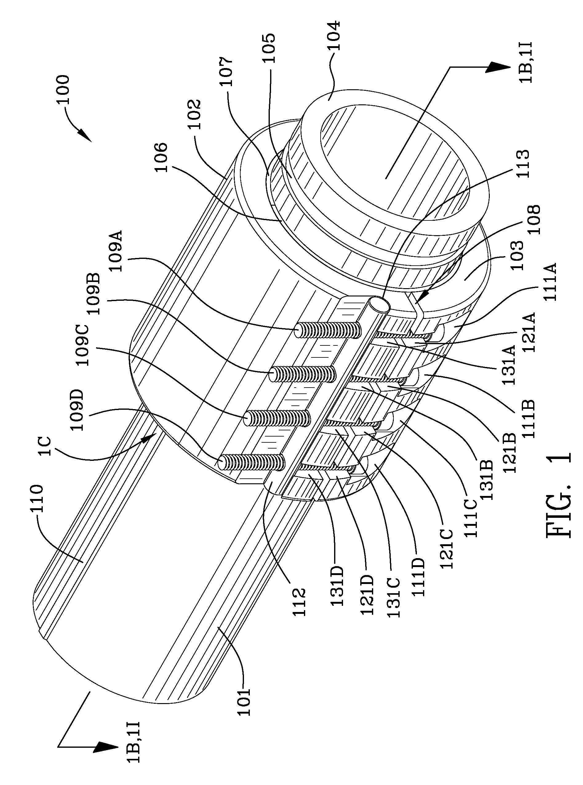
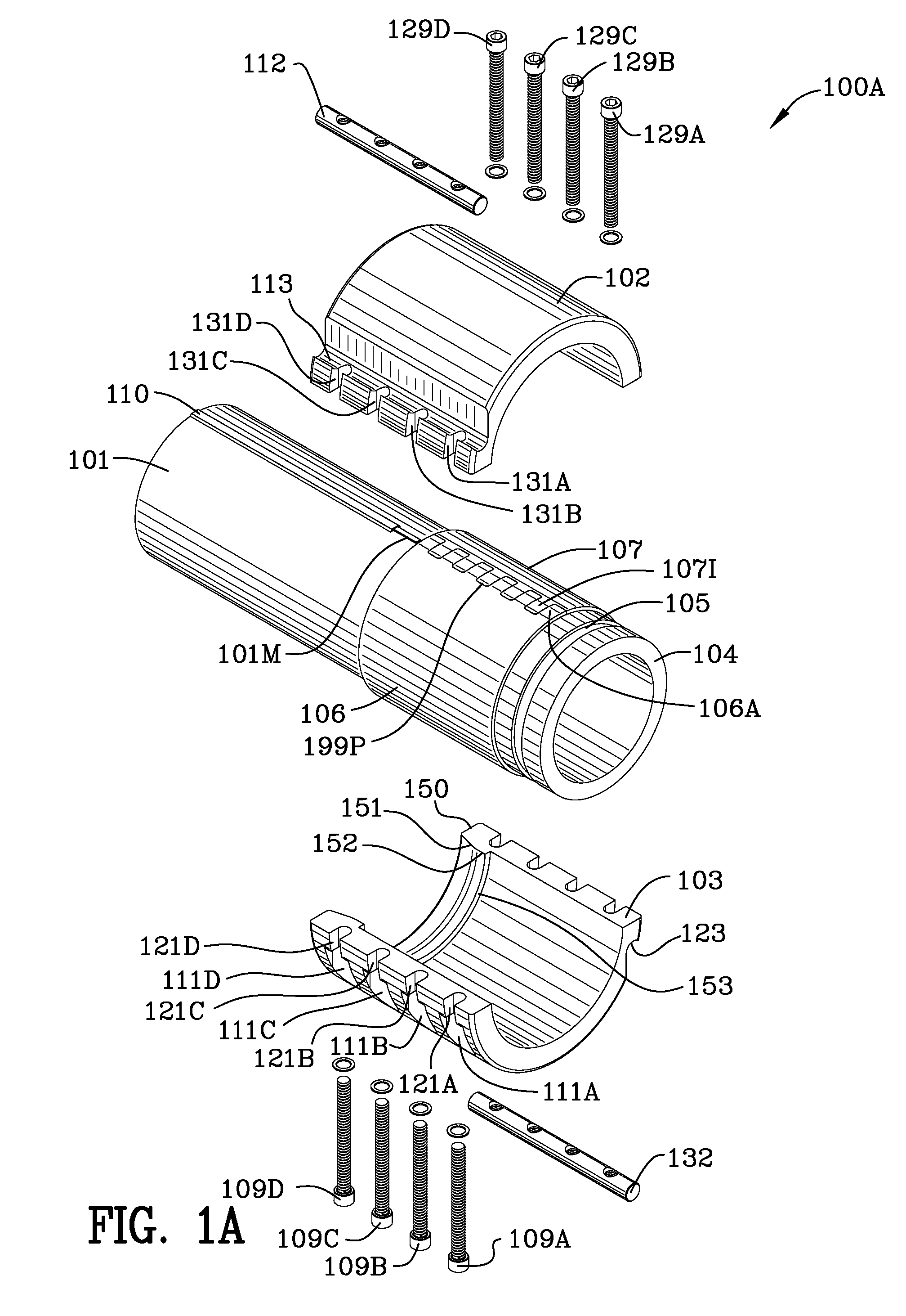
[0058]FIG. 1 is a front perspective view 100 of the coupling, sleeve halves 106, 107, tailpiece 104, hose 101, and collar 102, 103. The collar is made of two halves, a first collar half 102 and a second collar half 103. The collar halves and tailpiece may be made of any conductive metal such as aluminum or other non-corroding metal. The sleeves 106, 107 may be made of nylon or non-corroding metal such as aluminum. A grounding conductor 101M is illustrated as being slightly raised from the hose surface. The grounding conductor 101M electrically communicates any electrical potential through the conductor as well as all metal components in communication with the conductor 101M such as the collar half 102, tailpiece 104 and sleeve half 106.

[0059]FIG. 1C is cross-sectional view 100C taken of the area denoted by reference numeral 1C in FIG. 1. The metal grounding conductor 101M is copper, aluminum or some other highly conductive metal and is illustrated in cross-section in engagement with...


PUM


Abstract

The hose includes an outer jacket which includes warp and weft fibers made of Vectran®. The process for making the hose, includes: forming an inner liner and coating the exterior thereof with adhesive; weaving, in a twill weave pattern, Vectran® yarn, in a repeating 2-4-2-4-2 pattern in both the warp and the weft directions; extruding polyurethane onto the woven vectran yarn, the polyurethane extending into pillars between the warp and weft yarn, forming an outer liner; inserting the inner liner coated with adhesive within the outer liner; and, pressurizing the inner liner with steam expanding the inner liner and the adhesive into engagement with the Vectran® yarn and polyurethane pillars of the outer liner.

Description

FILED OF THE INVENTION[0001]This invention is in the field of hoses and hose couplings.BACKGROUND OF THE INVENTION[0002]U.S. Pat. No. 4,940,261 to Sommer-Vine states in the Abstract that: “[t]his invention relates to a pipe coupling and, in particular, to a Victaulic-type coupling which generally comprise a pair of half shells, together forming a sleeve which can be placed around adjacent flanged or grooved ends of a pair of pipes which have been located in co-axial end to end relationship for joining. The pipe coupling of the invention comprises a pair of discrete, substantially identical half shells which are engageable with one another to form a coupling sleeve. The half shells each include a hook formation on one end thereof which is interengageable with the hook formation of the other half shell, partly to secure the half shells to one another.”[0003]U.S. Pat. No. 5,297,822 to Sanders et al. discloses in the Abstract that: “[a] hose construction, coupling therefor and methods o...

Claims


Application Information

Patent Timeline
Patent Type & Authority Patents(United States)
IPC IPC(8): F16L11/00B29C48/06B29C48/34
CPCB29C47/28B29C63/18F16L11/085F16L33/23B32B37/02B29C47/0023Y10T156/10B29C47/0057B29C47/021B29C2063/485B29D23/001B29K2075/00B29K2105/0845B29K2995/0072B29L2023/005B29C47/065B29C47/067B29C47/0033B29C48/34B29C48/09B29C48/13B29C48/0018B29C48/21B29C48/22B29C48/151B29C48/06F16L11/02
Inventor LOCKHART, MARKSCHOMAKER, JOSEF
Owner ALL AMERICAN HOSE ACQUISITIONS LLC
Why Eureka
Try Eureka