Segmented insert for intervertebral support

a support and segment technology, applied in the field of support inserts, can solve the problems of no disc morselization and intervertebral bone growth promotion, and achieve the effect of facilitating outward bending

Active Publication Date: 2012-12-11
MAZOR ROBOTICS
View PDF28 Cites 128 Cited by
  • Summary
  • Abstract
  • Description
  • Claims
  • Application Information

AI Technical Summary

Benefits of technology

[0015]Once the screw is in place, further support is provided in the form of a pile of elements, strung on the screw like a pile of washers, and added inside the intervertebral disc space, so that the compression load between vertebrae is carried partly by these washer-like elements. This increases spine stability, reduces the loads on the screw in those cases where the screw too is used for support, and can assist in achieving decompression. These inter-vertebral washer-like elements are inserted through the bore in which the screw was is inserted, onto the screw shank in a tightly folded configuration, and are deployed into their flat washer-like form only when in position in the intervertebral space. The washer-like elements are therefore inserted through the same hole as the screw, without the need for any additional incisions. The bore is typically of the order of 6 mm in diameter, such that the procedure is minimally invasive. Since the bore is drilled from the pedicle of one vertebra and directed obliquely to the disc space, the washer-like element insertion is not performed in the transverse plane, as is a common practice for prior art cage insertion.
[0037]In any of those implementations of methods involving the use of cylindrical elements with slotted walls, that end of the cylinder from which the longitudinal slots commence may advantageously be chamfered in a direction which assists in the radially outward bending of the slotted sections of the wall. Furthermore, the rod may have a sloped shoulder to contact the chamfered end of the cylinder, to assist in the radially outward bending of the slotted sections of the wall.

Problems solved by technology

The difference between these procedures is that whereas fusion requires insertion of bone-grafting material to encourage intervertebral bone growth, in the case of dynamic stabilization, no disc morselization is generally performed, or only sufficient to leave space for the intervertebral body, nor is any intervertebral bone-growth promotion used.

Method used


Image

  • Segmented insert for intervertebral support
  • Segmented insert for intervertebral support
  • Segmented insert for intervertebral support

Examples


Embodiment Construction

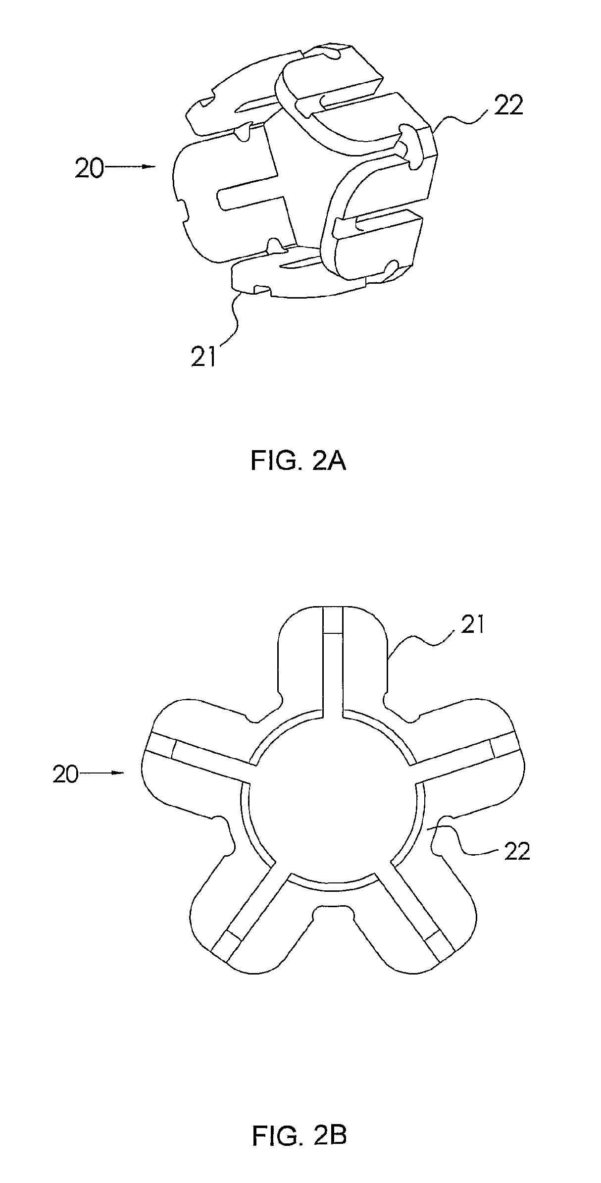
[0050]Reference is now made to FIGS. 2A and 2B, which illustrate schematically the two stages of an exemplary cylindrical segmental element 20, before and after deployment. FIG. 2A shows the element 20 with its leaves 21 folded, such that it can be inserted over the shank of the screw and through a hole drilled in the cortical bone of the pedicle of a vertebra. Once the leaves 21 protrude from the vertebra body into the disc space, they can expand into the disc space, making the segmental element almost flat and washer-like, and with a substantially larger diameter than that of the screw hole through which they were inserted. The element may be made of either a flexible or a rigid material. The leaves are connected by joints 22, which enable the leaves to rotate relative to each other around an axis parallel to their circumferential point of joining. The joints 22 can be either thinner or more flexible sections of the elements, or actual mechanical joints such as miniature revolute ...


PUM


Abstract

A spinal intervertebral support implant, for fusion or for dynamic stabilization purposes. A rod, preferably in the form of a screw, is inserted obliquely from the pedicle of an inferior vertebra into the body of a neighboring superior vertebra, through the disc space. The rod can be anchored into the body of the superior vertebra by means of a force fit or a screw thread. A pile of elements is disposed on the rod in the disc space like a pile of washers, so that the compression load between vertebrae is carried partly by these elements. These elements can be inserted through the bore through which the rod was inserted in a tightly folded configuration, and deployed into their washer-like form only when in position in the intervertebral space, such that there is no need for any additional incisions.

Description

[0001]This is a 35 U.S.C. §371 application of PCT / IL2009 / 000292, filed Mar. 15, 2009, and claims the benefit under 35 U.S.C. §120 of said PCT application, and further claims the benefit under 35 U.S.C. §119(e) of U.S. Provisional Patent Application USSN 61 / 064,610, filed Mar. 14, 2008. The contents of these priority applications are incorporated herein by reference.FIELD OF THE INVENTION[0002]The present invention relates to the field of support inserts for stabilizing or fusing adjacent vertebrae, especially using elements inserted under minimally invasive procedures.BACKGROUND OF THE INVENTION[0003]Stabilization of the spine generally utilizes implants such as screws, cages, hooks, spacers, and other devices, to stabilize two or more adjacent vertebrae. Traditionally, two adjacent vertebrae are fixed to each other in a stable, mutual position, and fusion is induced by means of bone growth. Recently, dynamic stabilization of the spine has also been introduced, in which two vertebra...

Claims


Application Information

Patent Timeline
Patent Type & Authority Patents(United States)
IPC IPC(8): A61B17/88A61B17/70A61F2/44
CPCA61F2/4455A61F2/44A61F2002/30172A61F2002/30446A61F2002/30471A61F2002/30563A61F2002/30579A61F2002/30596A61F2002/30599A61F2002/30604A61F2002/3085A61F2002/4415A61F2220/0041A61F2220/0091A61F2230/0052A61F2250/0063A61F2002/30433A61F2002/30594
Inventor ZEHAVI, ELISHOHAM, MOSHE
Owner MAZOR ROBOTICS
Why Eureka
Try Eureka