
Multi-purpose plasmonic ambient light sensor and visual range proximity sensor

a technology of ambient light sensor and plasmonic light, which is applied in the direction of optical radiation measurement, pulse technique, instruments, etc., can solve the problem that it is not feasible to use the ambient light sensor as a detector part of the proximity sensor, and achieve the effect of improving the spectral response of the ambient light sensor and saving power or battery li

Inactive Publication Date: 2012-12-11
NANOLAMBDA
View PDF12 Cites 36 Cited by
  • Summary
  • Abstract
  • Description
  • Claims
  • Application Information

AI Technical Summary

Benefits of technology

"The patent describes a plasmonic ambient light sensor that can be used in mobile devices to improve their response and save battery power. The sensor has a spectral response close to the human eye, which allows it to detect objects placed near the device. This sensor can also be integrated with a visible light emitter to create a proximity sensor that can lock the device's touch screen when near a human face or save battery power by turning off the display screen when near objects. The invention also provides a plasmonic ambient light sensor that can be used as a detection part of a proximity sensor, saving space and components within the mobile device."

Problems solved by technology

Since the working wavelength range, IR(Infra Red), for proximity sensor and the target wavelength range, visual, of the spectral response of the ambient light sensor are different, it is not feasible to use the ambient light sensor as a detector part of the proximity sensor.

Method used


Image

  • Multi-purpose plasmonic ambient light sensor and visual range proximity sensor
  • Multi-purpose plasmonic ambient light sensor and visual range proximity sensor
  • Multi-purpose plasmonic ambient light sensor and visual range proximity sensor

Examples


Embodiment Construction

[0015]Unless otherwise specified, the words “a” or “an” as used herein mean “one or more”. The term “light” includes visible light as well as UV and IR radiation. The invention includes the following embodiments.

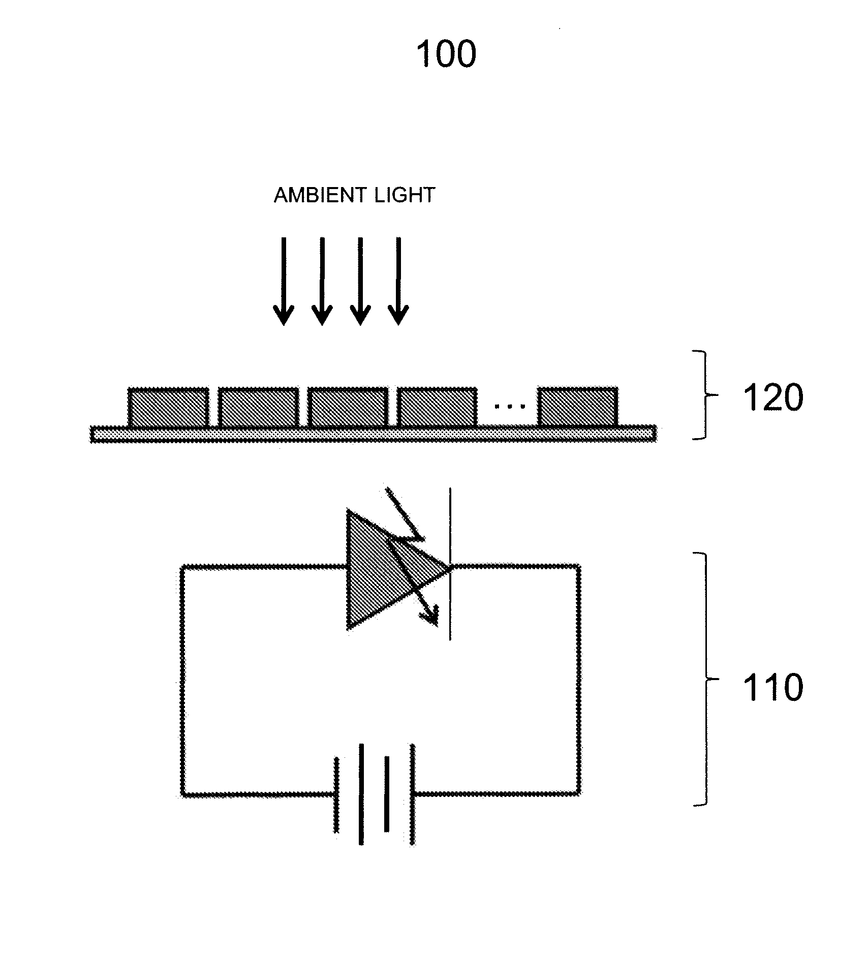
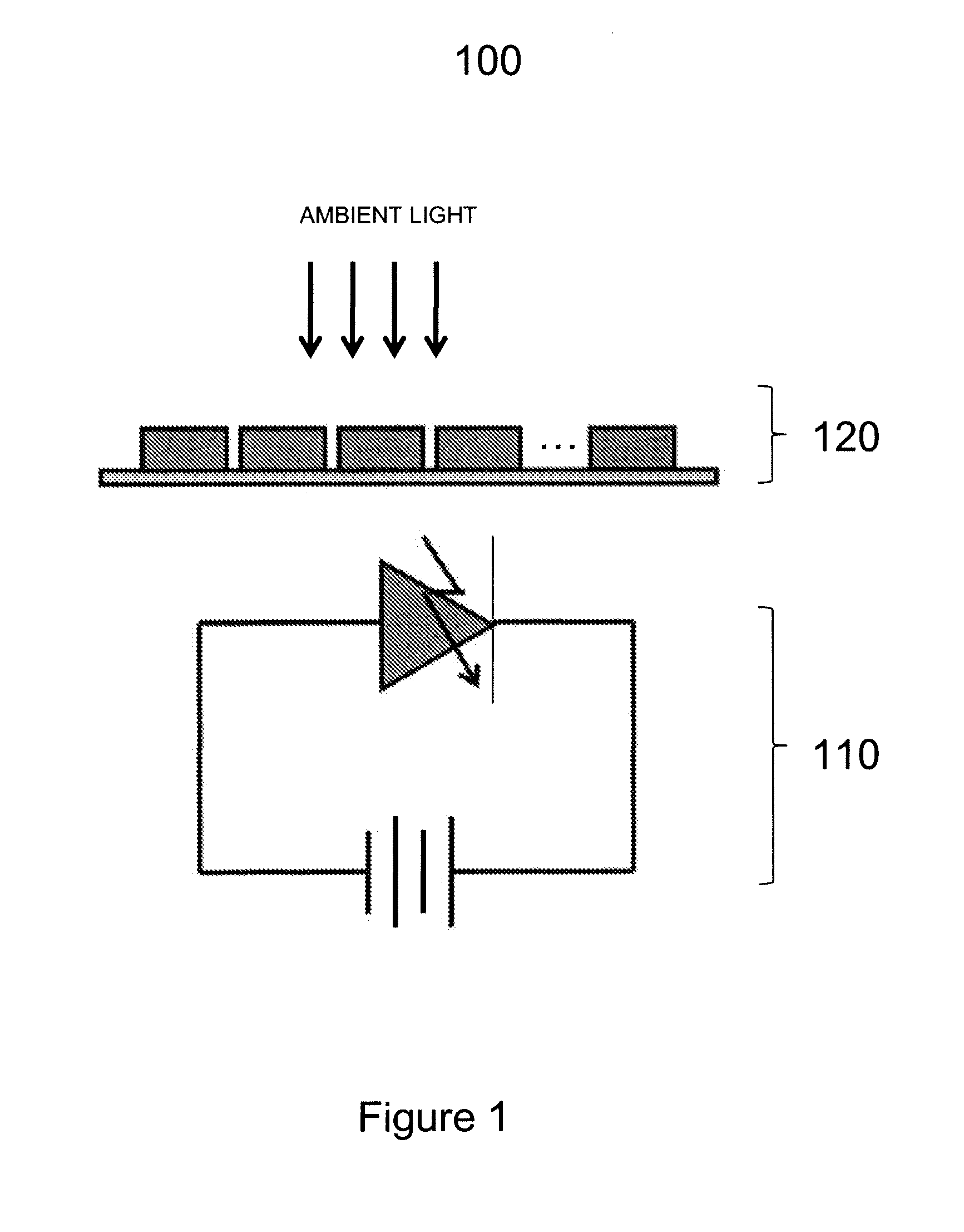
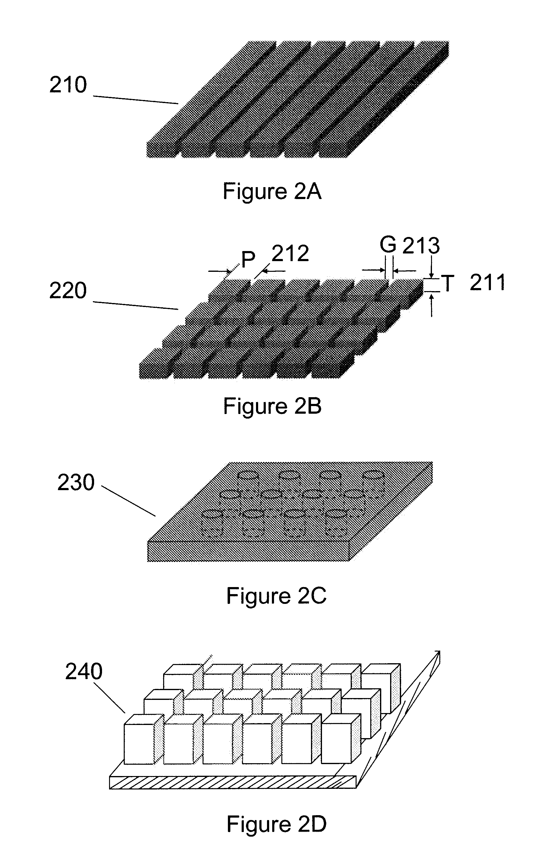
[0016]In FIG. 1, a plasmonic ambient light sensor 100 is shown containing a photodetector 110 and a plasmonic optical filter device 120. The examples of plasmonic optical filter structures are shown in FIGS. 2A, 2B, 2C and 2D.

[0017]Any suitable plasmonic optical filter structures may be used. Non-limiting examples of such filter structures are described in the following patent applications, which are incorporated by reference herein in their entirety:

[0018]WAVELENGTH SELECTIVE METALLIC EMBOSSING NANOSTRUCTURE, PCT patent application serial number PCT / US2007 / 026135 filed on Dec. 21, 2007 which claims priority to U.S. Provisional Application Ser. No. 60 / 877,660, filed on Dec. 29, 2006;

[0019]PLASMONIC FABRY-PEROT FILTER, PCT patent application serial number PCT / US2007 / 026071 fi...


PUM


Abstract

A visible wavelength range proximity sensor includes a visible light emitter with a peak wavelength in a visible wavelength range, and a plasmonic ambient light sensor, where a proximity sensing mode and an ambient light sensing mode are time multiplexed.

Description

CROSS-REFERENCE TO RELATED PATENT APPLICATIONS[0001]The present application claims benefit of U.S. provisional application 61 / 064,732, filed Mar. 24, 2008, and is a U.S. national stage application of Patent Cooperation Treaty application PCT / US2009 / 037621, filed Mar. 19, 2009, which are incorporated herein by reference in their entirety.BACKGROUND OF THE INVENTION[0002]Ambient light sensing has traditionally been used in industrial applications involving photometry, and over the years was incorporated in some consumer electronics appliances involving displays such as LCDs, FPDs, plasma displays, HDTVs, computer displays, camcorders etc., for brightness control. Lately, the concept has started to appear in handheld devices such as PDAs, MP3 players, PMP players and mobile phones. The inclusion of ambient light sensing provides a reduction in battery power usage, which is important given the introduction of power hungry color LCD displays. Studies have shown that backlighting is only ...

Claims


Application Information

Patent Timeline
Patent Type & Authority Patents(United States)
IPC IPC(8): G01J1/42
CPCB82Y20/00G01S7/4813G01S17/026G02B5/008G02B5/20G02B6/1226H01L31/0232H01L31/125H03K17/943G02B2006/12138H03K2217/94106H03K2217/94108G01S17/04H01L31/02327
Inventor CHOI, BYUNGSONG, MIN KYULEE, BYOUNGHEE
Owner NANOLAMBDA
Learn More