
Object detector

a technology of object detection and object edges, applied in the field of object detection apparatus, can solve the problems of difficult to estimate the depth information of an object photographed, difficult inability to accurately associate an object position area, etc., to achieve accurate association of object position area, reduce the variation of measurement points, and improve the accuracy of stereo measurement

Inactive Publication Date: 2012-12-11
TOKYO INST OF TECH +1
View PDF21 Cites 21 Cited by
  • Summary
  • Abstract
  • Description
  • Claims
  • Application Information

AI Technical Summary

Benefits of technology

The present invention provides an object detecting apparatus that can identify multiple objects in an image, even if they are in proximity to or partially overlap each other. It can accurately associate each object with a specific position in the image and track its movement over time. This allows for reliable detection and tracking of objects, regardless of their distance from the camera. Additionally, the apparatus can accurately determine the relative and absolute velocity of detected objects, which can help in identifying still objects and determining their motion.

Problems solved by technology

When a vehicle with an object detecting apparatus travels outside, object edges are not necessarily stably determined due to effects of shadows or the like resulting from brightness changes depending on the weather and time.
Thus, it is difficult to estimate an object area.
Further, since the image captured by a camera is two-dimensional information, depth information of an object photographed is lost.
Therefore, when motion of a plurality of objects is to be observed in the image using an optical flow or the like, the motion of the objects often cannot be traced due to effects of the proximity or the overlapping in the image.

Method used


Image

  • Object detector
  • Object detector
  • Object detector

Examples


Embodiment Construction

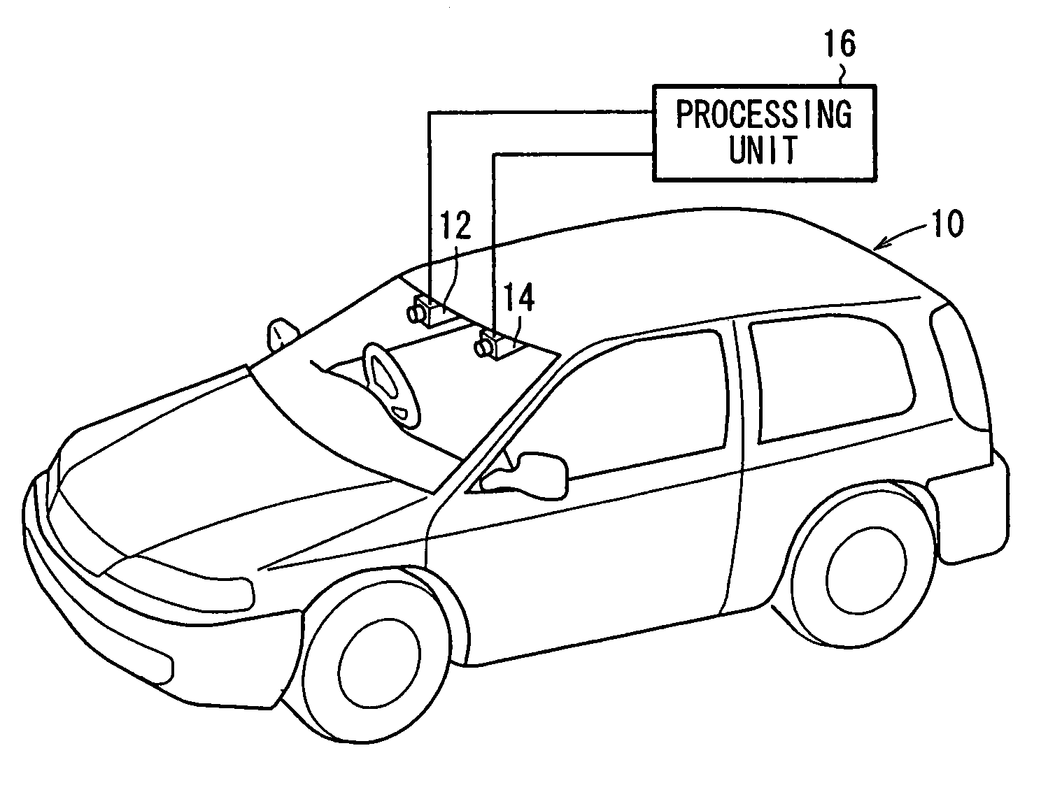
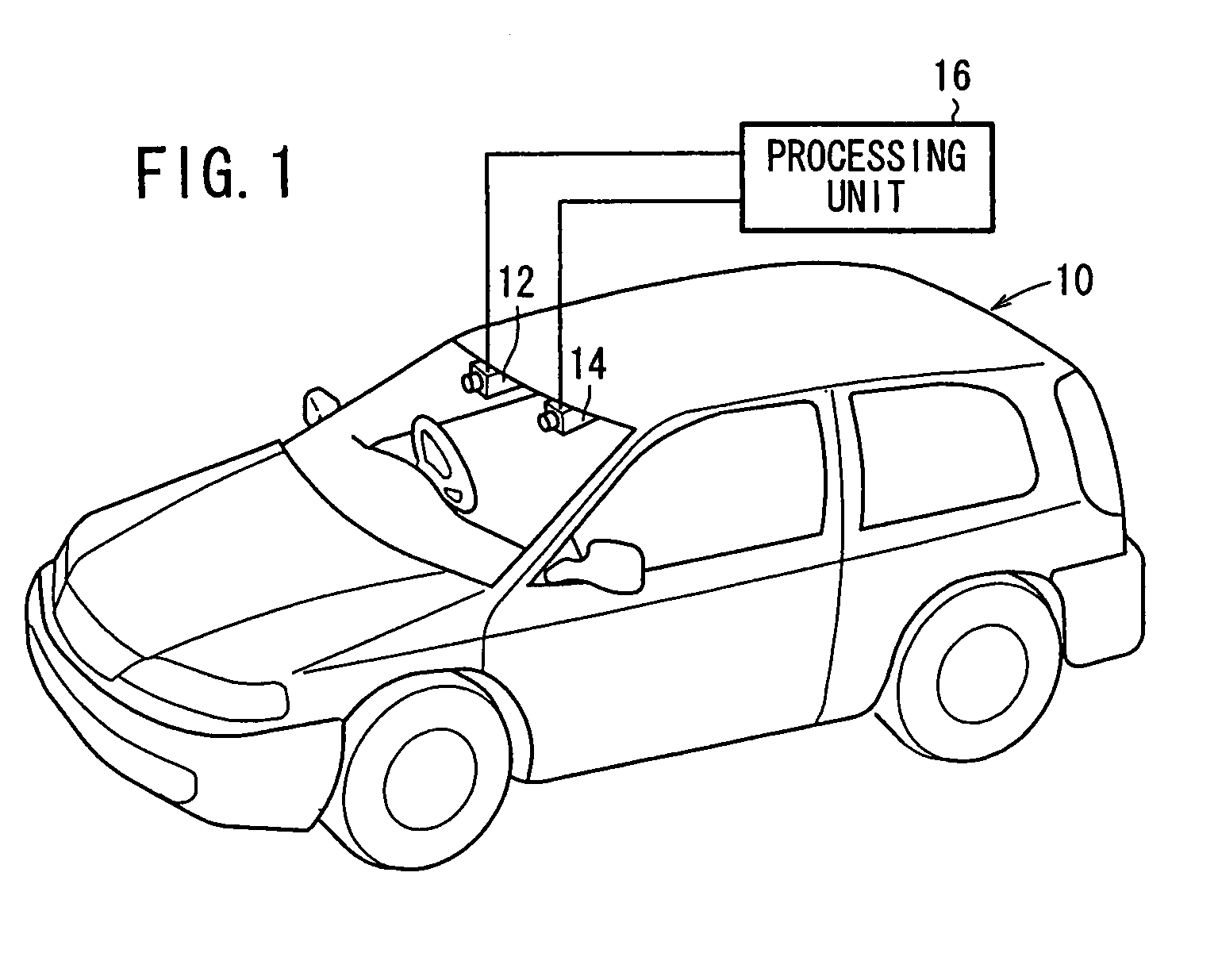
[0060]FIG. 1 shows a vehicle 10 according to an embodiment to which an object detecting apparatus according to the present invention is applied. The vehicle 10 has a windshield on which there are fixedly mounted a base camera 12 and a reference camera 14 in upper left and right regions thereof as a pair of image capturing means for capturing images including a road plane area where the vehicle 10 travels. The base camera 12 and the reference camera 14 are stereo cameras comprising CCD cameras or the like with a common image capturing area set therein. The base camera 12 and the reference camera 14 are connected to a processing unit 16 for processing captured images to detect the road plane area and an object which may possibly become an obstacle. In the description which follows, an image captured by the base camera 12 will be referred to as a base image, and an image captured by the reference camera 14 as a reference image.

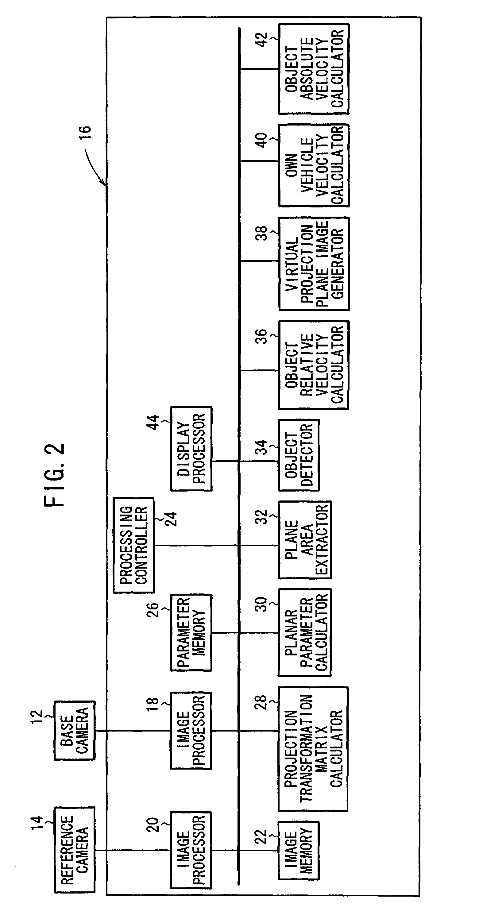
[0061]FIG. 2 is a functional block diagram of the processin...


PUM


Abstract

An object position area is calculated according to a position in the space of a detected truck. A template corresponding to the object position area recorded at the previous time is then called. The template is moved to a position on a reference image Ib where the similarity is highest. Overlap rate of the object position area and the template is calculated. A decision is made whether the object is identical to that detected in the past by using the overlap rate.

Description

TECHNICAL FIELD[0001]The present invention relates to an object detecting apparatus for detecting a peripheral object based on an acquired image.BACKGROUND ART[0002]Processes for detecting a road plane area that can be traveled or detecting an obstacle that is present in a traveling environment in guiding a mobile object such as an automobile or the like are roughly classified into processes using a laser radar, ultrasonic waves, a milliwave radar, etc., and processes using images.[0003]The detecting processes using a laser radar and a milliwave radar are problematic in that the apparatus used are generally expensive and a sufficient spatial resolution cannot be achieved. The detecting processes using ultrasonic waves are problematic in that it is difficult to make measurements in distant ranges and the spatial resolution is low.[0004]The processes using images are grouped into single-eyed processes and double-eyed processes. Heretofore, many of the processes using images employ an ...

Claims


Application Information

Patent Timeline
Patent Type & Authority Patents(United States)
IPC IPC(8): G06K9/00G06K9/36G06K9/62
CPCG06K9/00805G06T7/0044G06K2009/3291G06T7/74G06V20/58G06V10/62
Inventor SEKI, AKIHITOOKUTOMI, MASATOSHI
Owner TOKYO INST OF TECH
Learn More