Exhaust heat recovery device

a heat recovery device and exhaust heat technology, applied in the direction of engines, mechanical equipment, machines/engines, etc., can solve the problems of difficult to facilitate the heating of the catalyst, delay in the heat generation of the catalyst, etc., and achieve the effect of early heating of the catalys

Inactive Publication Date: 2012-12-18
DENSO CORP
View PDF21 Cites 16 Cited by
  • Summary
  • Abstract
  • Description
  • Claims
  • Application Information

AI Technical Summary

Benefits of technology

[0005]In view of the foregoing problems, it is an object of the present invention to provide an exhaust heat recovery device which can realize both of an early heating of a catalyst and prevention of a boiling of coolant.
[0007]Because the evaporation portion is configured to be capable of cooling the catalyst, a super-heating of the catalyst can be suppressed by the heat recovery unit. Furthermore, because the control unit causes the flow adjusting portion to adjust the flow amount of the operation fluid from the condensation portion to the evaporation portion at zero in the catalyst heating mode, the exhaust gas is not cooled in the evaporation portion, thereby facilitating the heating of the catalyst when the temperature of the catalyst is lower than the first threshold value. Furthermore, because the flow amount of the operation fluid from the condensation portion to the evaporation portion is set at zero by the flow adjusting portion, the heat exchange amount between the coolant (operation fluid) and the exhaust gas can be set substantially at zero, thereby preventing the boiling of the coolant.

Problems solved by technology

Conversely, if the flow amount is adjusted by the coolant flow adjusting unit to a value without causing the boiling of the coolant, the heating of the catalyst may delay.
Thus, it may be difficult to facilitate the heating of the catalyst while preventing the boiling of the coolant, in the above exhaust heat recovery device.

Method used


Image

  • Exhaust heat recovery device
  • Exhaust heat recovery device
  • Exhaust heat recovery device

Examples


first embodiment

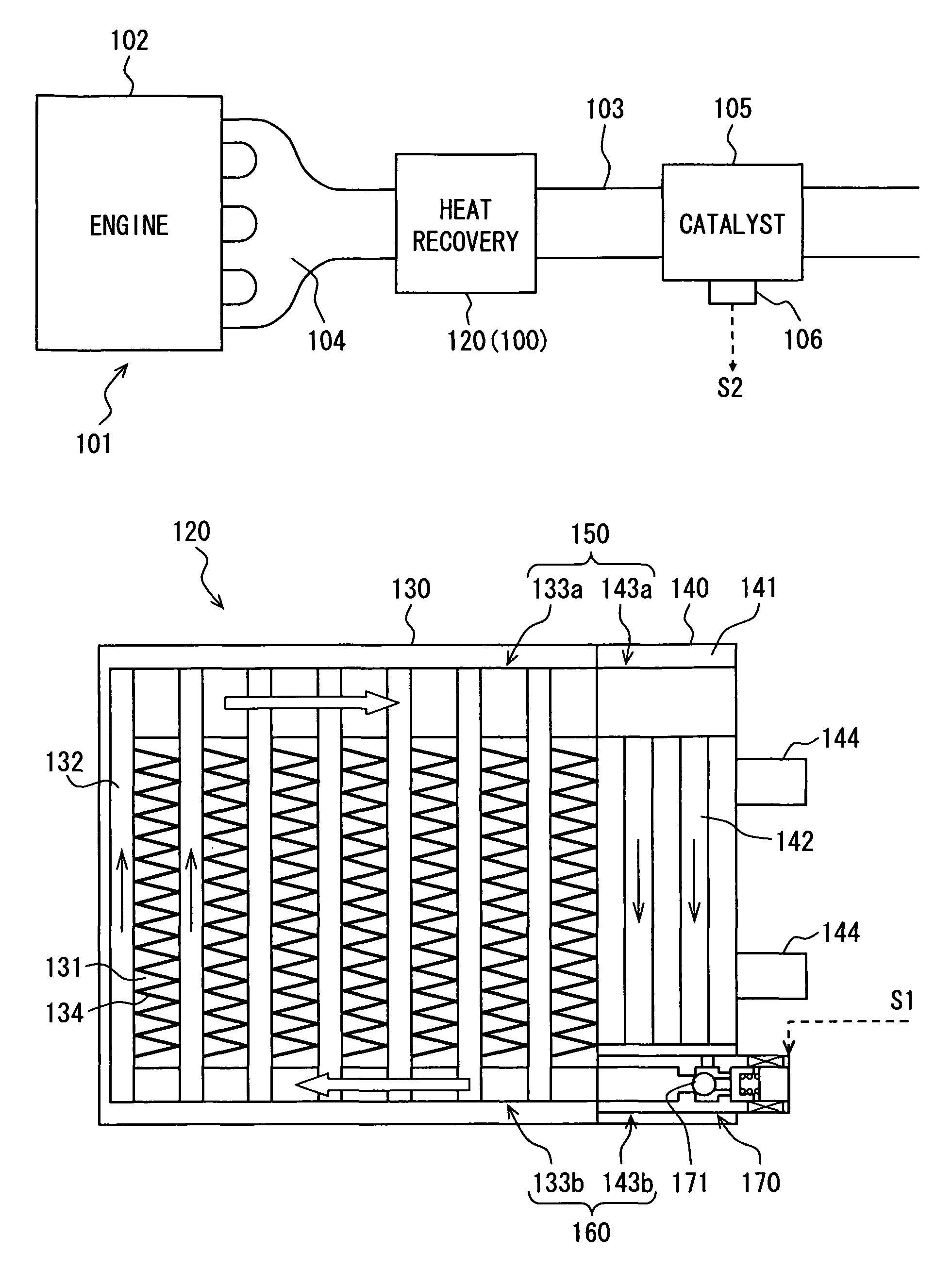
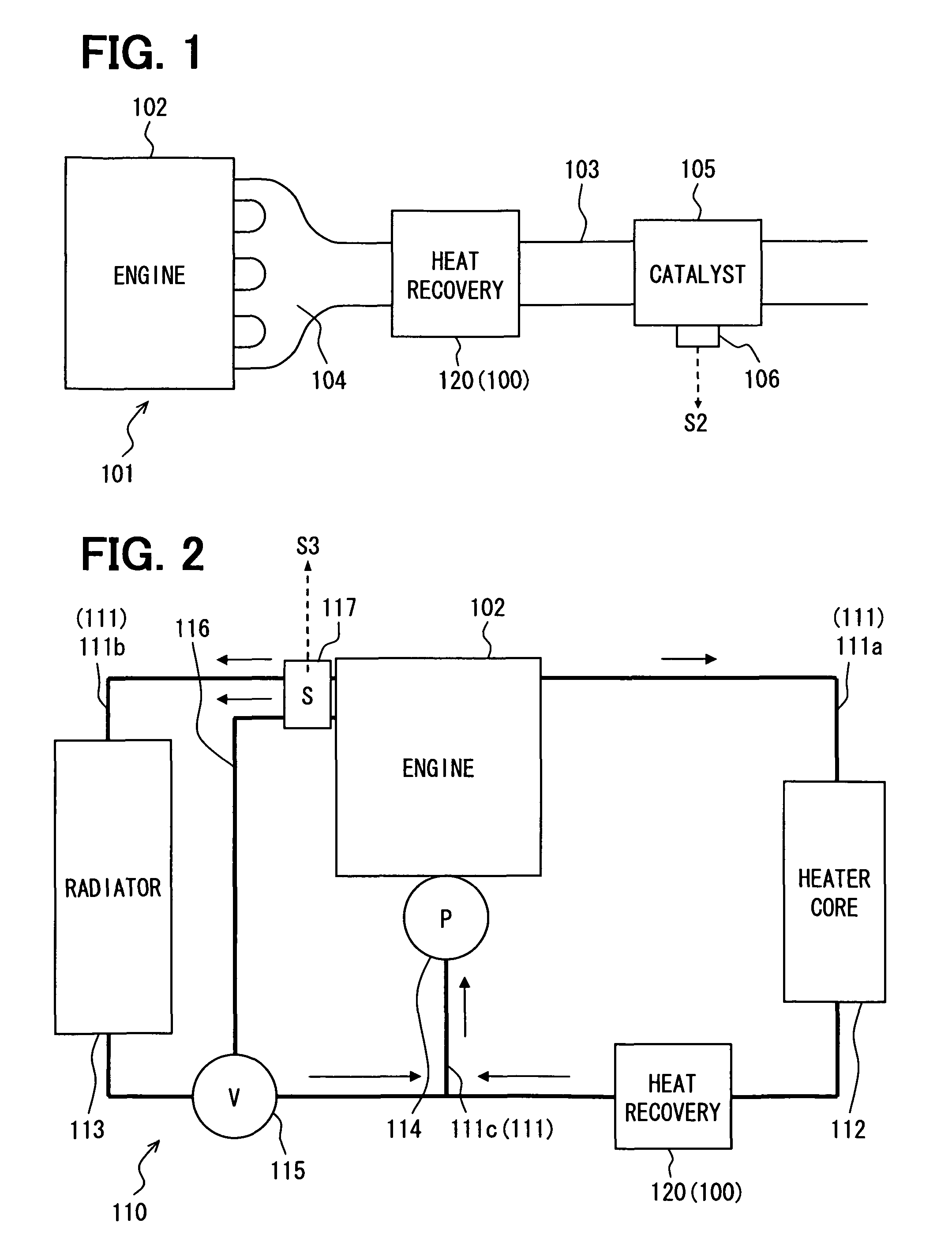
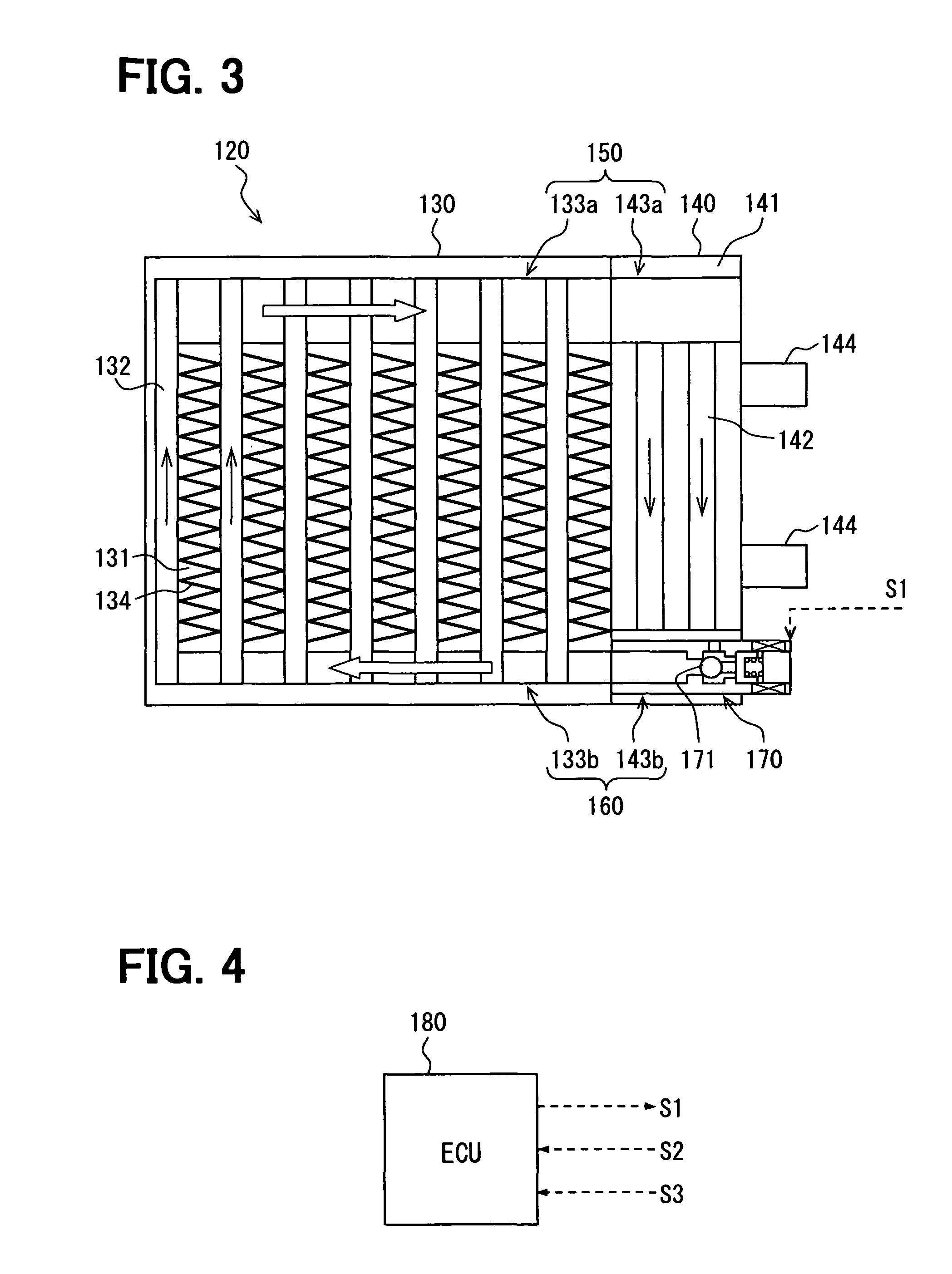
[0022]A first embodiment of the present invention will be described with reference to FIGS. 1 to 5E. First, an exhaust heat recovery device 100 according to the first embodiment will be now described. In the first embodiment, the exhaust heat recovery device 100 is typically used for an exhaust gas system 101, as shown in FIG. 1. As shown in FIG. 2, the exhaust heat recovery device 100 is located in a coolant system 110 of an engine 102 of a vehicle. In FIG. 2, the arrows indicate the flow of the coolant. The exhaust heat recovery device 100 includes a heat recovery unit 120 shown in FIG. 3 and a control unit 180 shown in FIG. 4, for example.

[0023]The exhaust gas system 101 is provided with the engine 102 that is an internal combustion engine, an exhaust gas pipe 103 in which exhaust gas discharged from the engine 102 flows, a catalyst 105 located in the exhaust gas pipe 103 to purify the exhaust gas flowing through the exhaust gas pipe 103, and the heat recovery unit 120. The heat ...

second embodiment

[0058]An exhaust heat recovery device 200 according to an example of a second embodiment of the present invention will be described with reference to FIG. 6. In FIG. 6, the parts similar to or corresponding to those of the first embodiment are indicated by the same reference numbers as in the first embodiment, and the detail explanation thereof is omitted.

[0059]The exhaust heat recovery device 200 includes a heat recovery unit 220 that includes an evaporation portion 230, in which an operation fluid is capable of being evaporated by absorbing heat from the exhaust gas, and the condensation portion 140. The evaporation portion 230 is located on a surface of the exhaust gas pipe 103 at a position between the exhaust manifold 104 located at one end side of the exhaust gas pipe 103 and the catalyst 105 in the exhaust gas pipe 103. The evaporation portion 230 is located to cover an outer wall surface of the exhaust gas pipe 103 at a portion, so that the exhaust gas flowing in the exhaust...

third embodiment

[0064]An exhaust heat recovery device 300 according to an example of a third embodiment of the present invention will be described with reference to FIG. 7. In FIG. 7, the parts similar to or corresponding to those of the first embodiment are indicated by the same reference numbers as in the first embodiment, and the detail explanation thereof is omitted.

[0065]The exhaust heat recovery device 300 includes a heat recovery unit 320 that includes an evaporation portion 330, in which an operation fluid is capable of being evaporated by absorbing heat from the exhaust gas, and the condensation portion 140. In the above-described second embodiment, the evaporation portion 230 is located on the surface of the exhaust gas pipe 103 at a position between the exhaust manifold 104 and the catalyst 105. However, in the third embodiment, the heat recovery unit 320 is located on a surface of the expansion manifold 104 that is an end portion of the exhaust gas pipe 103. The evaporation portion 330 ...


PUM


Abstract

An exhaust heat recovery device is provided with an evaporation portion for evaporating an operation fluid flowing therein by performing heat exchange with exhaust gas of an engine, a condensation portion for condensing the operation fluid flowing from the evaporation portion by performing heat exchange with coolant of the engine, and a flow adjusting portion for adjusting a flow amount of the operation fluid flowing from the condensation portion to the evaporation portion. A catalyst temperature detector is adapted to detect a temperature of a catalyst for purifying the exhaust gas, and a control unit sets a catalyst heating mode when the detected temperature of the catalyst is lower than a threshold value. Furthermore, the control unit causes the flow adjusting portion to adjust the flow amount of the operation fluid from the condensation portion to the evaporation portion at zero, in the catalyst heating mode.

Description

CROSS REFERENCE TO RELATED APPLICATION[0001]This application is based on Japanese Patent Application No. 2008-316185 filed on Dec. 11, 2008, the contents of which are incorporated herein by reference in its entirety.FIELD OF THE INVENTION[0002]The present invention relates to an exhaust heat recovery device for recovering heat from exhaust gas of an engine.BACKGROUND OF THE INVENTION[0003]Conventionally, an exhaust heat recovery device is known, for example, in JP 2008-190437A. The exhaust heat recovery device includes a heat recovery unit and a coolant flow adjusting unit. The heat recovery unit is located in an exhaust gas pipe of an internal combustion engine to perform heat exchange between coolant flowing therein and exhaust gas passing through the exhaust gas pipe. A catalyst is provided in the exhaust heat recovery device such that heating of the catalyst is performed by using exhaust gas in the exhaust gas pipe. The coolant flow adjusting unit is located to adjust a flow amo...

Claims


Application Information

Patent Timeline
Patent Type & Authority Patents(United States)
IPC IPC(8): F01N3/02
CPCF01N3/0205F01N3/2046F01N5/02F01N3/2889F01N2240/02Y02T10/16Y02T10/26Y02T10/12
Inventor MURAMATSU, KENSHIROUYAMANAKA, YASUTOSHIKOHARA, KIMIOMUKOUBARA, YUUKI
Owner DENSO CORP
Why Eureka
Try Eureka