Transducer with shield
a transducer and shield technology, applied in the field of high intensity focused ultrasound transducers, can solve the problems of health risk to patients, attenuation and thermal build-up, and loss of proper focus of ultrasound energy
- Summary
- Abstract
- Description
- Claims
- Application Information
AI Technical Summary
Benefits of technology
Problems solved by technology
Method used
Image
Examples
example i
[0060]The process of converting an existing HIFU transducer is shown starting in FIG. 6A. Here the transducer T is shown mounted in a housing. A mold with an aperture 120 is fitted over the face of the transducer T and housing 16. Desirably the riser 102 touches the transducer front face when the guide ring is properly fit around the transducer housing. The mold with aperture 120 is desirably secured to the transducer housing so the mold will not move or become unstable during the process steps which follow. Once the mold with aperture 120 is properly placed over the transducer, the surface of the transducer may be roughened to promote physical adhesion of the shield later on. Various mechanisms may be used to roughen the transducer surface. Methods using lasers, chemicals, mechanical etching (such as sand blasting shown in FIG. 6C), or grinding (FIG. 6C′) may be used.
[0061]The back of the transducer may be treated in a similar fashion allowing for the removal of...
example ii
Aperture with Filler
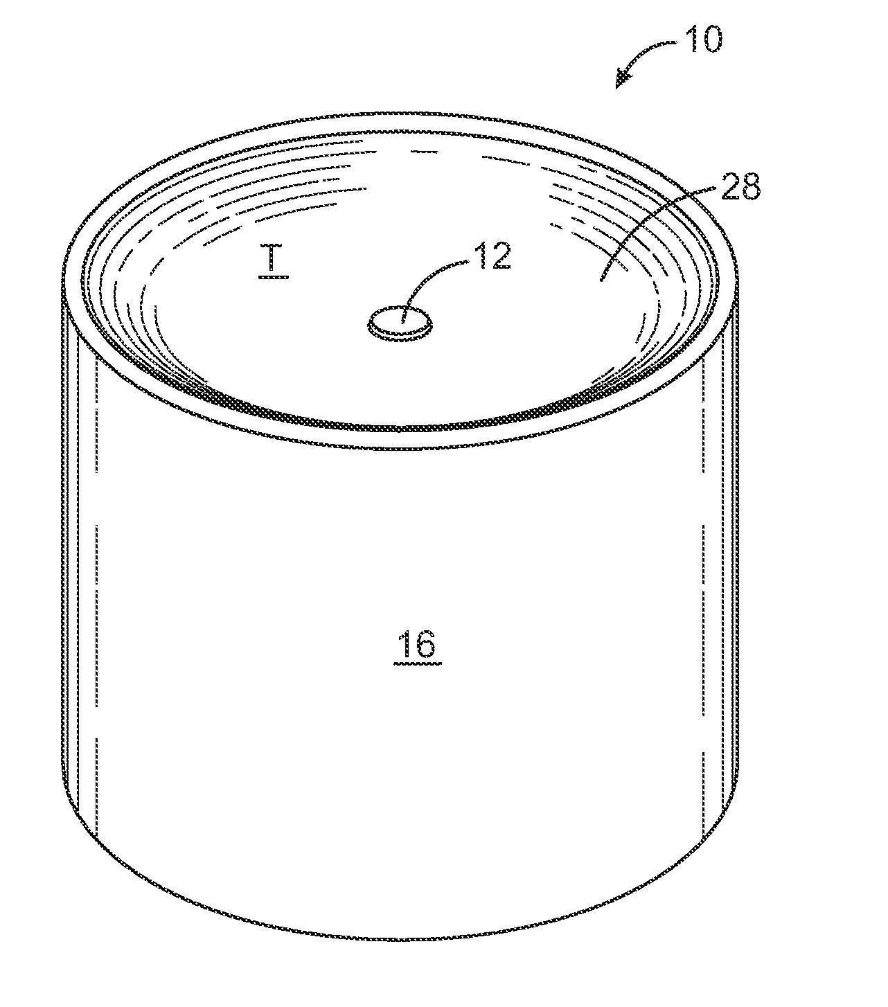
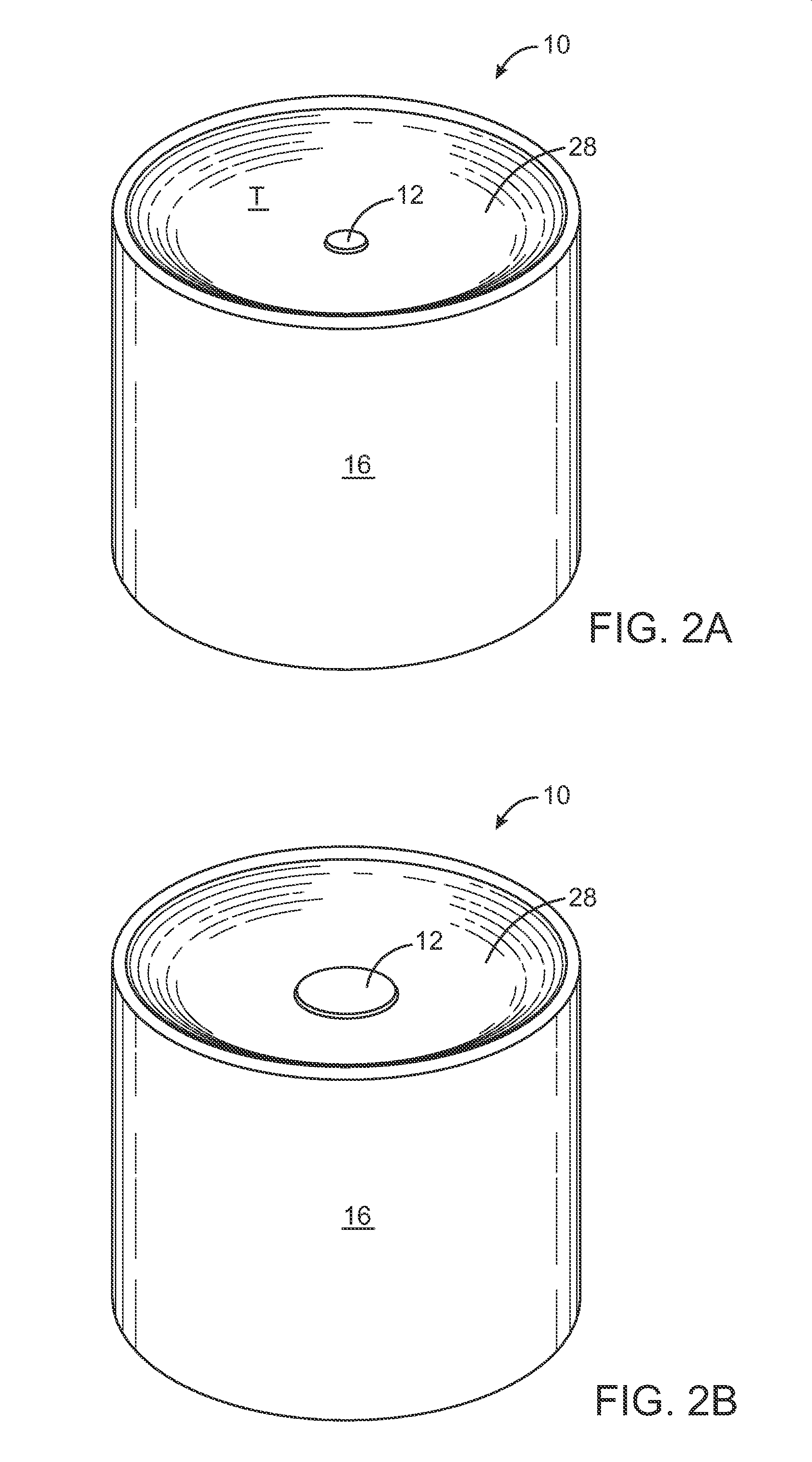
[0064]In another example, the transducer with a shield may be formed by removing the region of the transducer which is designated to be non-driven. This can be accomplished in a variety of ways. In one embodiment of creating the non-driven region by removal, the material within the volume of the transducer designated to be non-driven can be physically removed. The transducer may be supported in any appropriate fashion and the appropriate volume removed by drilling it out, cutting it out, or otherwise destroying that designated volume of piezoelectric material
[0065]Once the appropriate volume has been removed, the edges of the aperture are desirably smoothed to provide an even edge for uniform ultrasound generation of the remainder of the transducer. The aperture may now be lined with a non conductive material to preserve the integrity of the circuit, and provide enhanced structural integrity around the rim of the aperture. In addition, the aperture may now be fil...
example iii
Non-Driven Ceramic
[0067]In yet another embodiment, the non-driven region may be created by purposely rendering the ceramic in the non-driven region unresponsive to electrical impulses by cutting the metallization layer prior to the poling step. This would cause an insulating gap in the metallization layer rendering the isolated portion electrically inactive. The desired polarizing effect within the isolated piezoelectric material would not be produced.
PUM
 Abstract
Description
Claims
Application Information
 - R&D
- Intellectual Property
- Life Sciences
- Materials
- Tech Scout
- Unparalleled Data Quality
- Higher Quality Content
- 60% Fewer Hallucinations
Browse by: Latest US Patents, China's latest patents, Technical Efficacy Thesaurus, Application Domain, Technology Topic, Popular Technical Reports.
© 2025 PatSnap. All rights reserved.Legal|Privacy policy|Modern Slavery Act Transparency Statement|Sitemap|About US| Contact US: help@patsnap.com


