Bragg mirror and method for producing a bragg mirror

Pending Publication Date: 2022-11-03
COMMISSARIAT A LENERGIE ATOMIQUE ET AUX ENERGIES ALTERNATIVES
View PDF0 Cites 0 Cited by
  • Summary
  • Abstract
  • Description
  • Claims
  • Application Information

AI Technical Summary

Problems solved by technology

This type of solution is not adapted for laser sources requiring high optical power since by reducing the cavity length, the optical power of the laser beam decreases.
On the other hand, for applications of the LiDAR (laser detection and ranging) type or medium-distance datacom applications of the 400G Ethernet type, this type of solution does not allow to obtain both sufficient power, typically greater than 100 mW, and a single-mode laser beam.
The features of the output mirror of the previous example no longer

Method used


Image

  • Bragg mirror and method for producing a bragg mirror
  • Bragg mirror and method for producing a bragg mirror
  • Bragg mirror and method for producing a bragg mirror

Examples


Embodiment Construction

[0062]Before starting a detailed review of embodiments of the invention, it is recalled that the invention according to its first aspect comprises in particular the optional features below which can be used in combination or alternatively:

[0063]According to one example, the corrugations are separated from each other so that the separation layer is exposed between said corrugations.

[0064]According to one example, the corrugations are encapsulated in an encapsulation layer based on the second material.

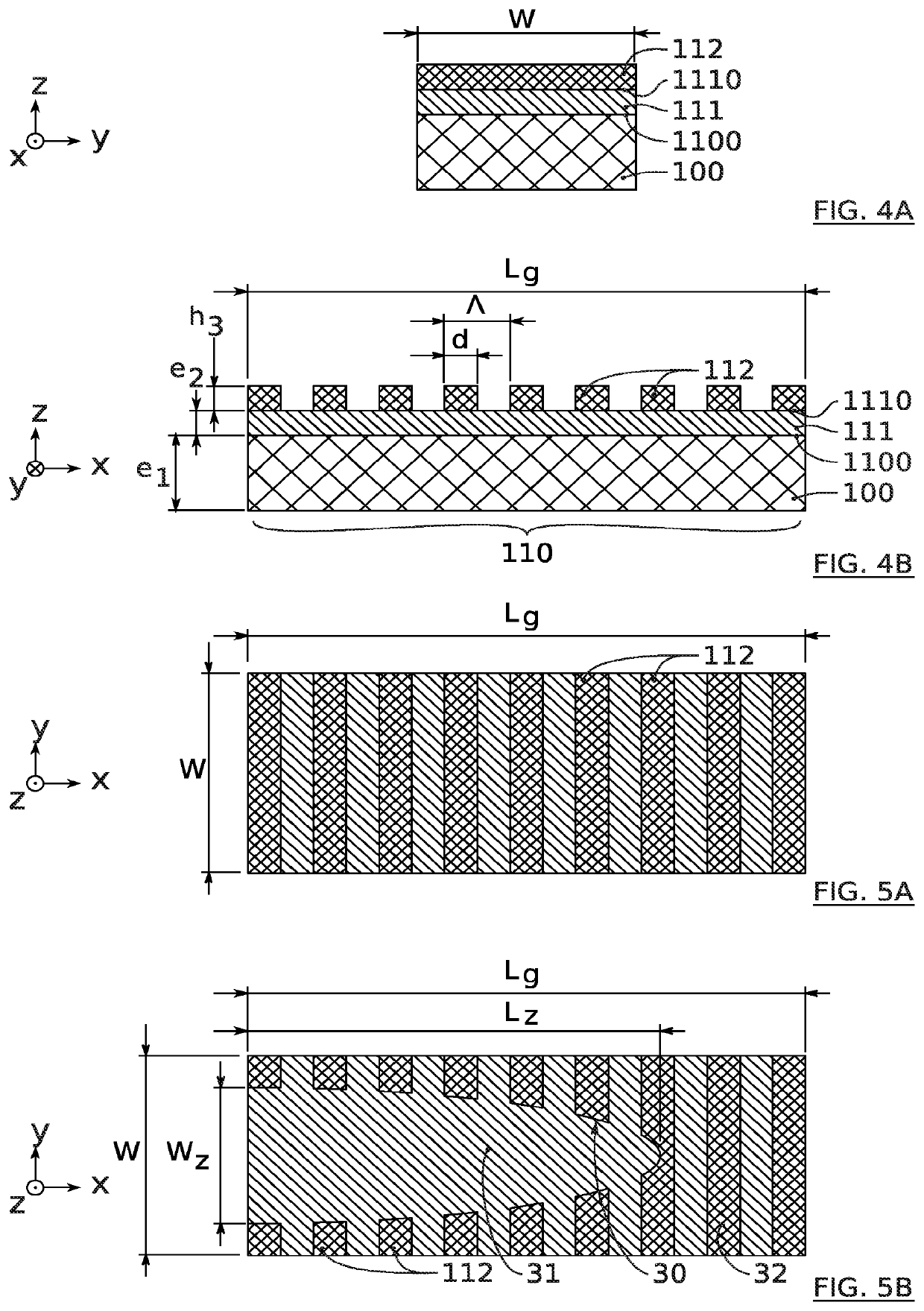
[0065]According to one example, the height h3 of the corrugations is greater than or equal to 5 nm and / or less than or equal to 30 nm.

[0066]According to one example, the thickness e2 of the separation layer is greater than or equal to 10 nm and / or less than or equal to 50 nm.

[0067]According to one example, the corrugations have an adiabatic pattern projecting in a main extension plane xy formed by the first and second directions x, y.

[0068]According to one example, the height h3 and the ...


PUM


Abstract

The invention relates to a Bragg mirror comprising a portion (110) of ribbon (100) having a refractive index n1, corrugations (112) having a refractive index n3 and a separation layer (111) separating the ribbon (100) from the corrugations (112) and having a refractive index n2, such that n2<n3 and n2<n1. The invention also relates to a method for producing such a mirror.

Description

TECHNICAL FIELD[0001]The present invention relates to the field of optoelectronics. It finds for particularly advantageous application the production of Bragg mirrors for semiconductor laser sources, for example for LiDAR (acronym for the expression “laser detection and ranging”) remote sensing lasers or for medium-distance datacom lasers of the 400G Ethernet type.PRIOR ART[0002]A Bragg mirror allows to reflect light radiation at normal incidence to said mirror, while limiting optical losses. It can thus have a reflectivity R greater than 99% for light radiation of given wavelength A.[0003]Bragg mirrors are therefore particularly advantageous for the manufacture of optical cavities for laser applications, and in particular for semiconductor laser sources.[0004]A known semiconductor laser source architecture is shown in FIGS. 1A, 1B. Such an architecture typically comprises a ribbon guide 100 extending longitudinally between two transverse Bragg mirrors 11, 12, and a Fabry-Perot type...

Claims


Application Information

Patent Timeline
IPC IPC(8): G02B5/18
CPCG02B5/1861G02B5/1847G02B6/122H01S5/125H01S5/021H01S5/141H01S5/1032
Inventor SCIANCALEPORE, CORRADOEL DIRANI, HOUSSEIN
Owner COMMISSARIAT A LENERGIE ATOMIQUE ET AUX ENERGIES ALTERNATIVES
Why Eureka
Try Eureka