Method for producing vias on flexible substrate

a flexible substrate and support technology, applied in the direction of basic electric elements, printed circuit non-printed electric components association, solid-state devices, etc., can solve the problems of incomplete filling of holes by liquid conductive ink, and may pose a problem for filling

Active Publication Date: 2020-04-21
COMMISSARIAT A LENERGIE ATOMIQUE ET AUX ENERGIES ALTERNATIVES
View PDF7 Cites 0 Cited by
  • Summary
  • Abstract
  • Description
  • Claims
  • Application Information

AI Technical Summary

Benefits of technology

[0015]The filling in two stages with liquids or inks of different viscosities makes it possible to avoid blocking the hole or the holes by the conductive ink and to allow the conductive element(s) to pass through the entire thickness of the substrate.
[0016]This also makes it possible to form an interconnection structure with improved conductance.
[0025]The hole or the holes may be produced so as to pass through the first conductive zone and the second conductive zone. This makes it possible to facilitate the contact pick up on the lower or upper face of the substrate.
[0026]Prior to the formation of the hole or the holes, at least one encapsulation layer is formed on the first conductive zone and / or on the second conductive zone, the hole or the holes being formed through the encapsulation layer. This or these encapsulation layers may serve as masking to the conductive filling liquid(s) in order to protect the face of the substrate on the side of which the filling takes place and to avoid the conductive liquid or the conductive ink being deposited on undesired regions of the device.
[0027]Advantageously, the hole or the holes is or are produced by mechanical drilling. This makes it possible not to damage the walls of the holes and thereby to favour subsequently the later treatment of these walls to make it possible to improve their wettability.

Problems solved by technology

In such devices, the filling of the holes by the liquid conductive ink may pose a problem.
When the substrate has an high thickness this filling generally proves to be incomplete, which can lead to the implementation of conductive elements of inhomogeneous transversal section and which sometimes do not entirely pass through the thickness of the substrate and thus do not emerge on both faces of the support.

Method used


Image

  • Method for producing vias on flexible substrate
  • Method for producing vias on flexible substrate

Examples


Embodiment Construction

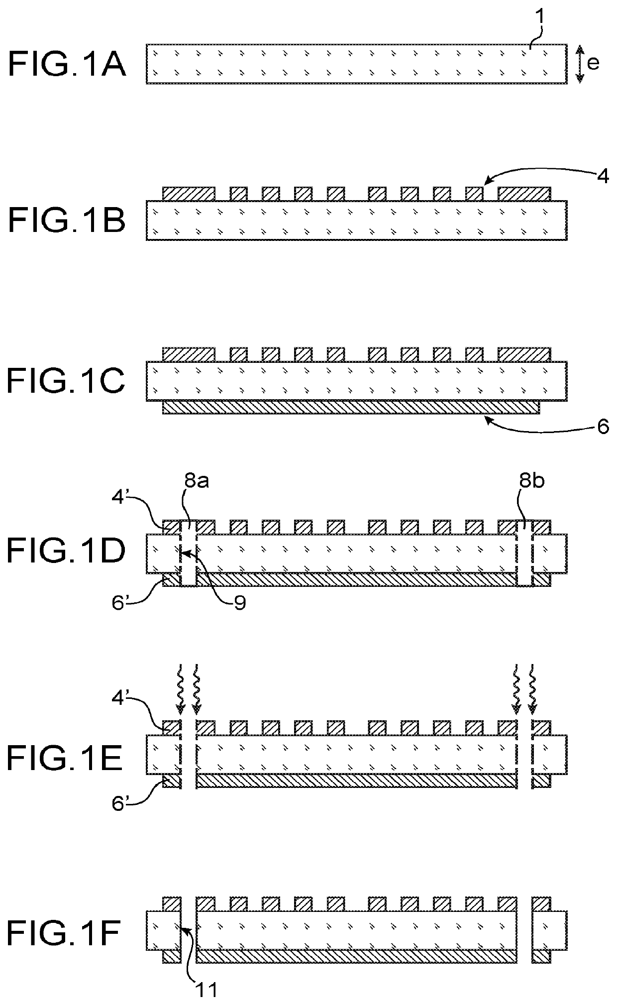
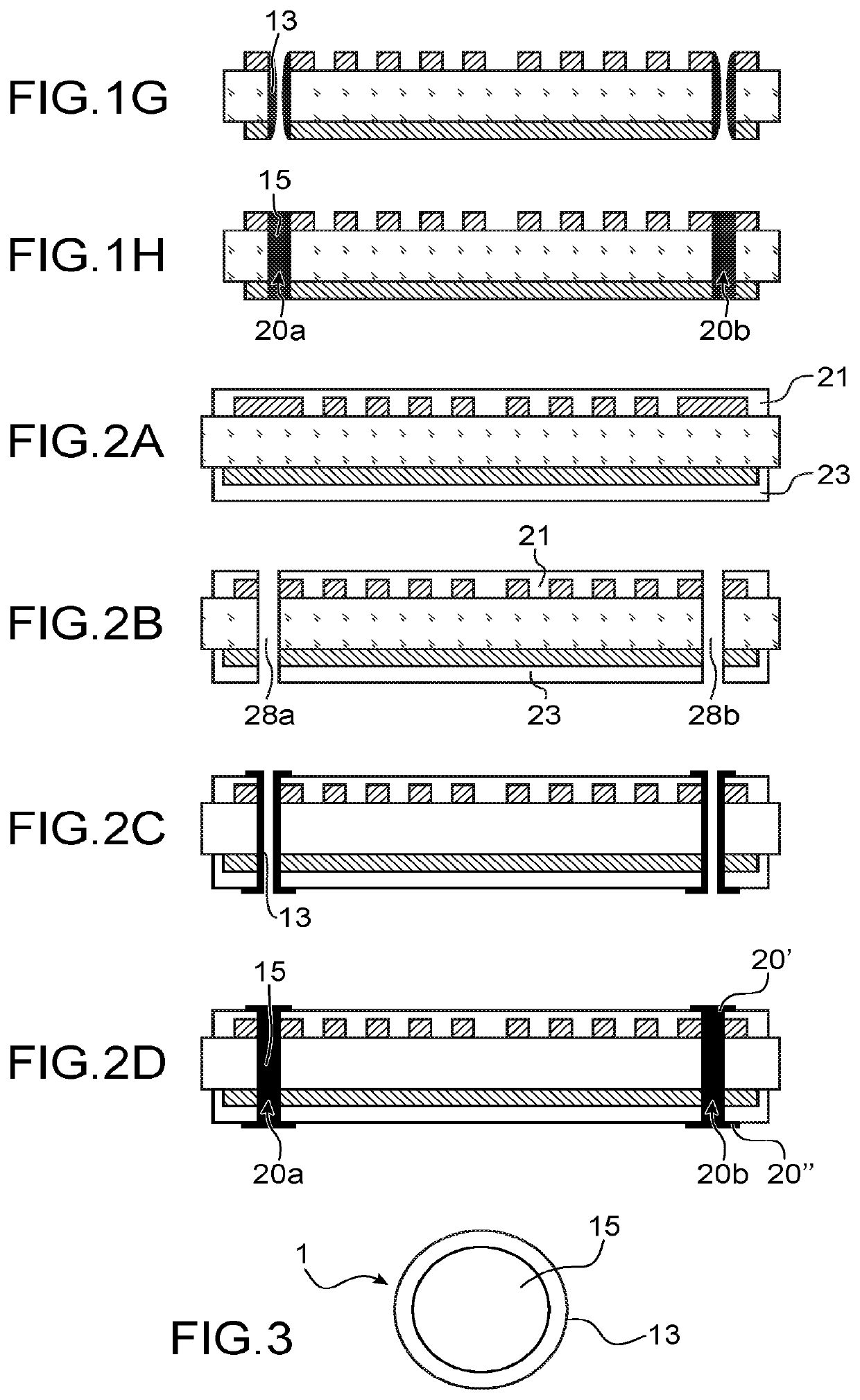
[0006]The present invention relates to the improved production of a connection structure for flexible or supple substrate.

[0007]According to one embodiment, it relates to a method comprising:

[0008]producing one or more holes passing through the thickness of the substrate,

[0009]depositing in the hole or the holes a first conductive liquid having a first viscosity,

[0010]depositing in the hole a second conductive liquid having a second viscosity greater than the first viscosity.

[0011]The first conductive liquid and the second conductive liquid are typically conductive inks.

[0012]The first conductive liquid has a first viscosity, in particular a low viscosity in order to form a layer on the wall or the walls of the hole or holes. This conductive layer is intended to form a conductive sheath or peripheral conductive portion of conductive elements passing through the substrate. The first viscosity is typically comprised between 0.2 and 100 mPa·s, preferably between 10 and 30 mPa·s.

[0013]T...


PUM

PropertyMeasurementUnit
viscosityaaaaaaaaaa
viscosityaaaaaaaaaa
viscosityaaaaaaaaaa

Abstract

Method for producing a connection structure passing through a flexible substrate, in particular a plastic substrate, comprising:producing a hole passing through the thickness of the substrate,depositing in the hole a first conductive ink having a first viscosity, so as to form a conductive layer on at least one wall of the hole,depositing in the hole a second conductive ink having a second viscosity greater than the first viscosity, so as to fill the hole.

Description

TECHNICAL FIELD AND PRIOR ART[0001]The present application pertains to the field of circuits produced on a flexible or supple support, in particular those formed on a plastic substrate.[0002]More specifically, it relates to an improved method for producing an interconnection structure passing through the thickness of a flexible support and applies notably within the context of the manufacture of circuits, in particular RF and / or electronic circuits, on such types of supports.[0003]To form a conductive element passing through the thickness of a substrate, it is known to produce a hole using a plasma or a laser or a chemical etching through the opening of a masking, then to fill this hole using a conductive material. In the field of circuits produced on a flexible support made of elastic, notably polymer, material, a conductive material in the form of liquid conductive ink is typically used to form connections.[0004]In such devices, the filling of the holes by the liquid conductive in...

Claims


Application Information

Patent Timeline
Patent Type & Authority Patents(United States)
IPC IPC(8): H01L21/48H01L23/498H01Q1/12H05K1/18H01Q23/00
CPCH05K1/189H01L23/49827H01L21/486H01Q1/12H01L21/4867H05K1/181H01Q23/00H01L23/4985
Inventor BENWADIH, MOHAMMEDHAON, OLIVIER
Owner COMMISSARIAT A LENERGIE ATOMIQUE ET AUX ENERGIES ALTERNATIVES
Why Eureka
Try Eureka