Charged particle beam apparatus

a technology of charge-beam apparatus and charge-beam radiation, which is applied in the direction of material analysis using wave/particle radiation, instruments, nuclear engineering, etc., can solve the problem of remaining deviant of charg

Active Publication Date: 2012-12-18
HITACHI HIGH-TECH CORP
View PDF15 Cites 45 Cited by
  • Summary
  • Abstract
  • Description
  • Claims
  • Application Information

AI Technical Summary

Benefits of technology

[0007]In addition, the proposal of Japanese Patent Application Publication No. 2007-059370 (corresponding to U.S. Pat. No. 7,187,345) makes it possible to restrain the local accumulation of charge; however, when the interval between scan lines is large, scan lines to be scanned in a position different in phase on a power-source variation curve are adjacent to each other.
[0008]A charged particle beam apparatus will be described below that is capable of restraining influences on an image caused by the accumulation of charge and the interval between scan lines sequentially scanned in time.

Problems solved by technology

However, because the time interval until the adjacent scan lines are formed is not sufficiently provided, there is a problem that the deviation of charge remains.

Method used


Image

  • Charged particle beam apparatus
  • Charged particle beam apparatus
  • Charged particle beam apparatus

Examples


Embodiment Construction

[0027]This application is based on the Japanese patent application JP2007-135916, all the contents of which are incorporated in this application by reference.

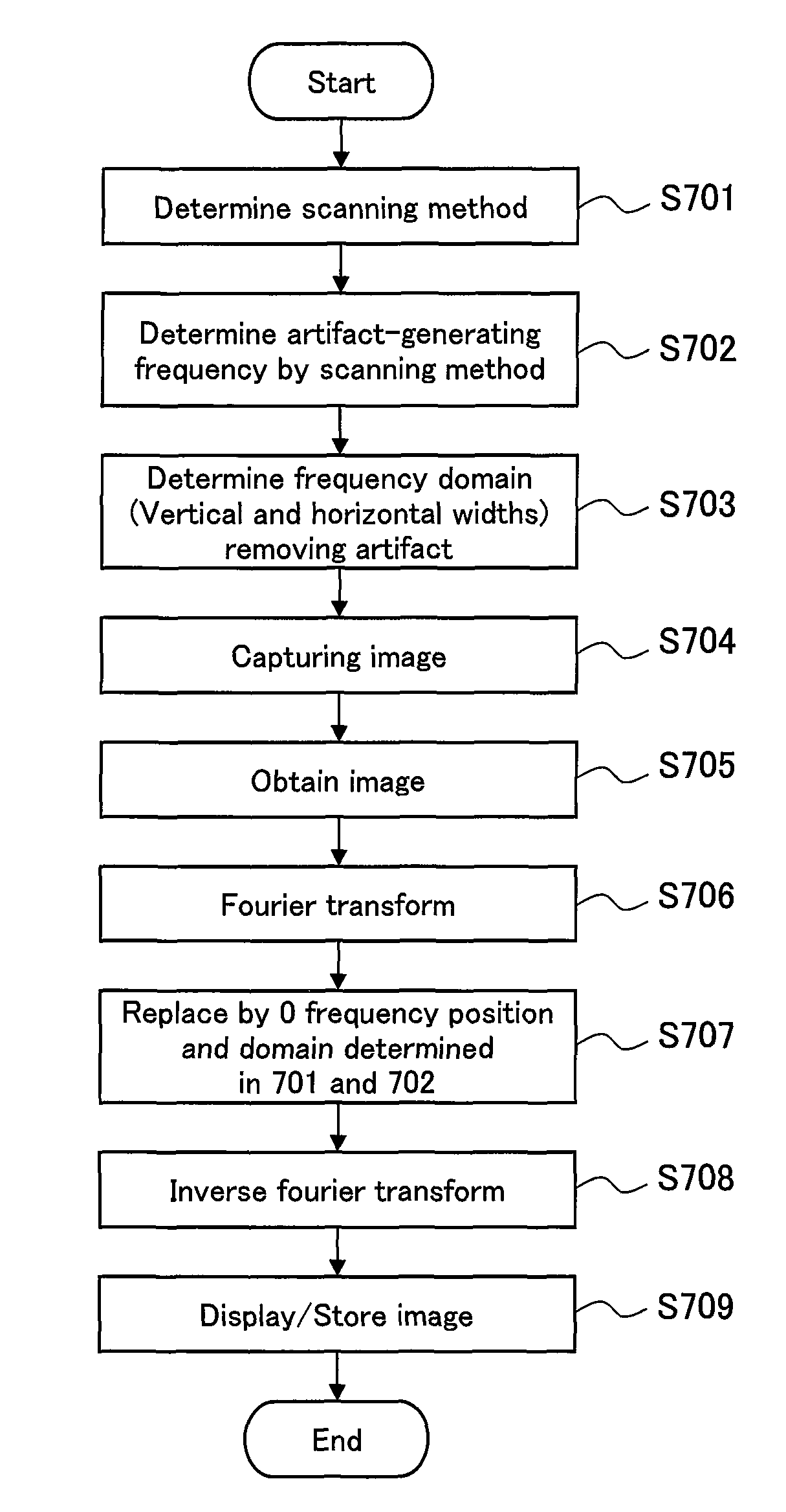
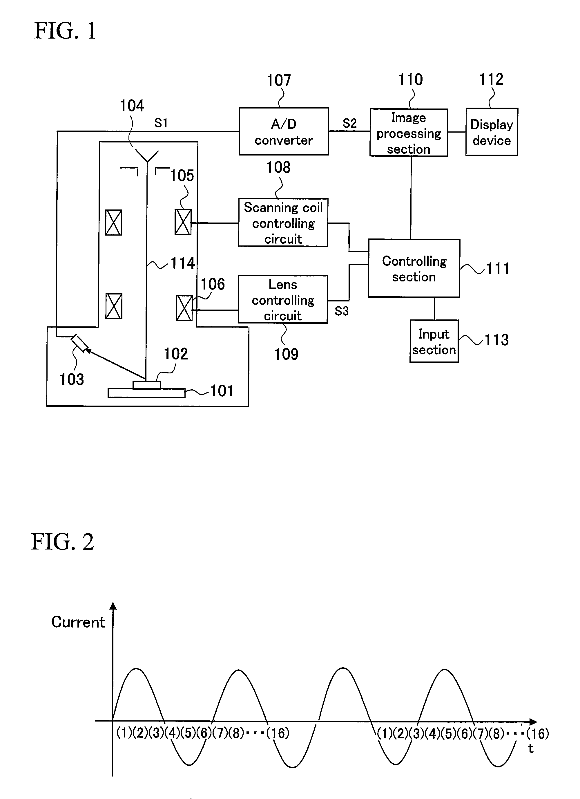
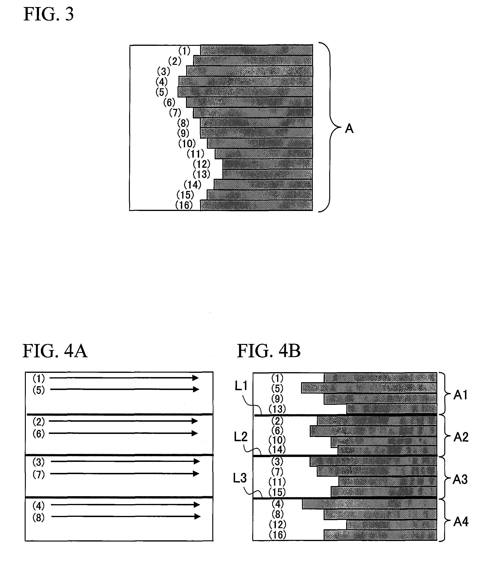
[0028]Before an embodiment of the present invention is described, a former patent application (Japanese Patent Application No. 2005-221185) for reducing the influence of charge will be described. With the use of the interlace scanning method disclosed in Japanese Patent Application Publication No. 2005-142038, the former application proposes a method and an apparatus for example, in which plural scan lines are scanned after each of the first, second and third scan lines is scanned. According to this constitution, with the presence of an interval in which plural scan lines are intervened relatively between the first, second and third scan lines, the influence of the residual charge from the first scan line to the other scan lines can be restrained. In addition, during the scanning of plural scan lines relatively between the firs...


PUM


Abstract

In a method and apparatus for removing artifacts from an image generated a charged partial beam scanning device, a scanning method is determined, and the frequency of an artifact appearing on an image can then be determined, based on scanning method. A step 703, a frequency domain for removing an artifact can be determined from the vertical and horizontal widths determined by experimentation in advance with respect to the frequency position Photography is performed to obtain an image, which is Fourier transformed and the determined frequency domain is replaced, for example, by “0.” The resulting image is subjected to inverse Fourier transformation, and displayed and stored. The flow of such processing enables decreasing an artifact appearing on an image, depending on a scanning method. The frequency domain (vertical and horizontal widths) that is to be eliminated and a method for replacement by “0” are determined in advance, depending on the kind of inspected samples and a method can be selected depending on the kind of samples.

Description

BACKGROUND OF THE INVENTIONField of the Invention[0001]The present invention relates to a charged particle beam apparatus and particularly relates to an image processing technique for removing artifacts generated due to the scanning method of a scan line.[0002]When an electron beam is irradiated on a sample to be inspected, a secondary electron is generated. A scanning electron microscope obtains an observation image of the surface of a sample by the use of a phenomenon in which a secondary electron yield varies depending on the shape of the sample. Here, in general scanning electron microscopes, scanning is performed for every line in a horizontal direction within a screen, in other words, in a raster direction (a horizontal line within a screen). Lines are scanned from the top to the bottom in a perpendicular direction within a screen.[0003]With the use of a general scanning method like this, a deviation in a perpendicular direction attributable to a charging phenomenon generated ...

Claims


Application Information

Patent Timeline
Patent Type & Authority Patents(United States)
IPC IPC(8): G06K9/40G06V10/98
CPCG01N23/225G06K9/00134G06K9/03H01J2237/221H01J2237/28G06V20/693G06V10/98
Inventor TAKANE, ATSUSHIIKEDA, MITSUJIKOBARU, ATSUSHI
Owner HITACHI HIGH-TECH CORP
Why Eureka
Try Eureka