
Safety system for machine tools

a safety system and machine tool technology, applied in the direction of band saws, metal sawing accessories, manufacturing tools, etc., can solve the problems of unworkable dils abandoned patent application, complex and expensive implementation, and likely subject to electrostatic and electromagnetic noise of the proposed flesh-detection method of Hauer disclosur

Active Publication Date: 2012-12-25
BUTLER DAVID J
View PDF15 Cites 28 Cited by
  • Summary
  • Abstract
  • Description
  • Claims
  • Application Information

AI Technical Summary

Benefits of technology

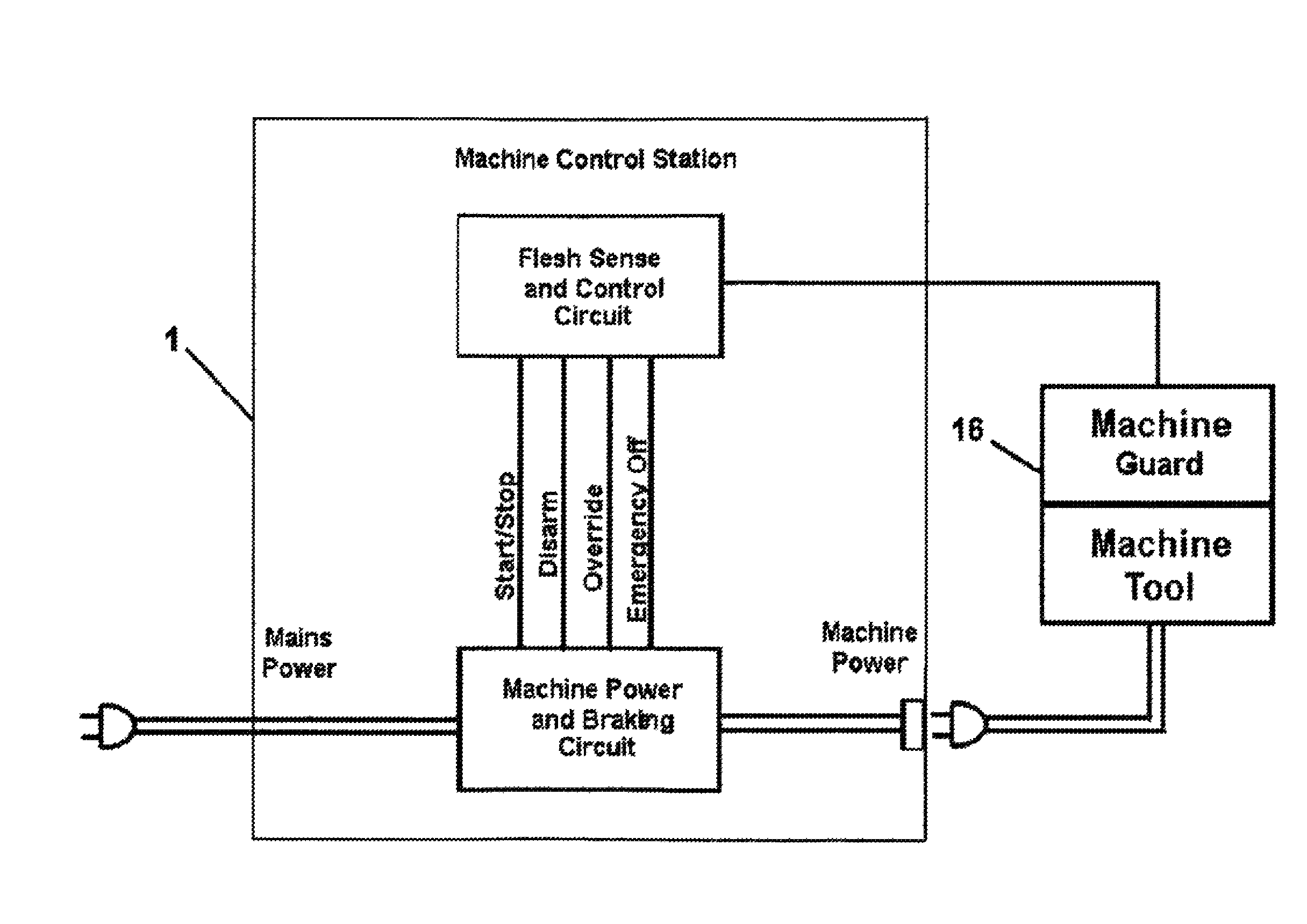
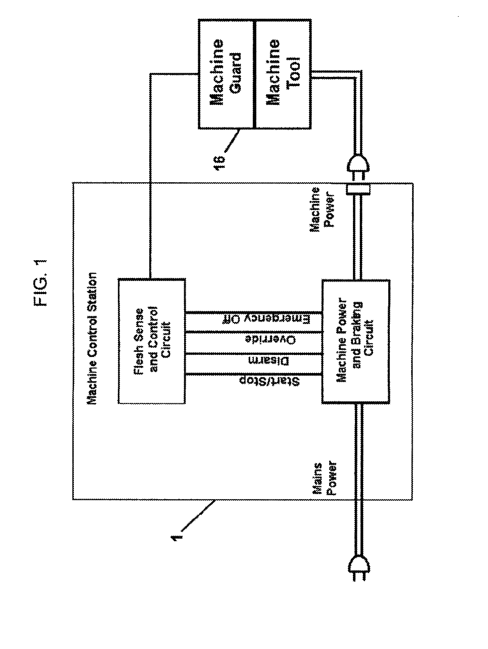
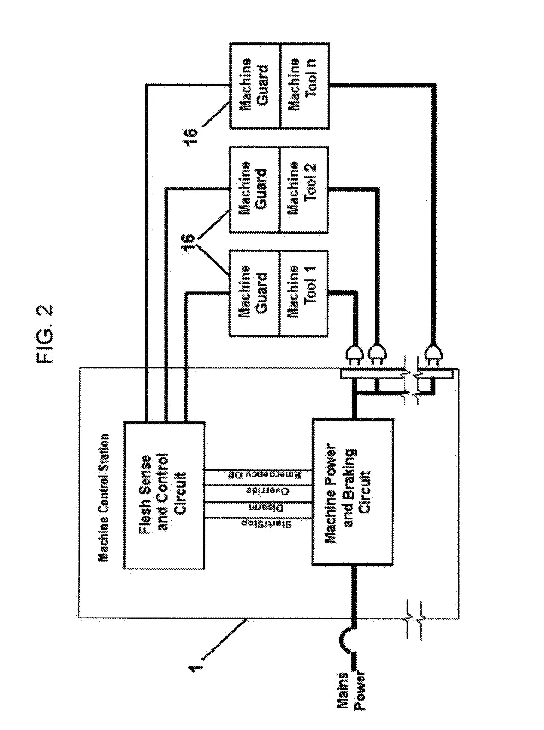
[0007]Accordingly, the present invention is a safety system for electric-motor powered machine tools and is intended to be used with existing machine tools, as well as for incorporation into new machine tool designs. The basic embodiment of this invention comprises an electrical operator control station, as well as a number of distinct and appropriate devices, adapted to interface with a respective type of machine tool, and incorporating a flesh-sensor which is electrically connected to the operator control station for precisely measuring operator contact or proximity to a dangerous portion of a machine tool. In addition, the present invention includes electric power control circuitry for rapidly braking a machine tool motor or initiating a machine-disabling electronic response as a result of flesh-detection.

Problems solved by technology

The HAUER disclosure's proposed flesh-detection method is likely subject to electrostatic and electromagnetic noise in a machine tool environment and is complex and would be expensive to implement.
The DILS abandoned patent application is unworkable due to various technical and electrical errors, including errors in the proposed method of rapidly stopping a machine motor.
Almost 90 years of no known commercial use, of the THEREMIN entertainment circuit method for human proximity detection, leads to the inescapable conclusion that the early device is impractical for such usage.
The NIEBERLE-HAUER application, now abandoned, fails to teach or suggest how to successfully implement a THEREMIN circuit in the electrically noisy environment of an electric-motor-driven table saw.
That disclosure is therefore non-enabling as a teaching of reliable capacitive flesh-sensing.

Method used


Image

  • Safety system for machine tools
  • Safety system for machine tools
  • Safety system for machine tools

Examples


Embodiment Construction

[0025]The basic embodiment of the invention is block-diagramed in FIG. 1 as a single machine tool safety system or in FIG. 2 as a multi-port machine tool safety system. The system of the present invention is made up of the following two main components: an electrical control safety station 1 suitable for use with electric-motor powered machine tools and a flesh-sensing machine guard 16 suitable for sensing presence of the operator's hands or body within close proximity to a dangerous portion of a machine tool, the machine guard being electrically connected to the control station. These components work together to create an architecture for the system that offers control, machine status indicators and flesh-sensing emergency braking or an alternative reaction which improves machine tool safety. It should further be noted that this invention embodiment may be electrically modified, according to the requirements of various classes of machine tools, with respect to parameters such as el...


PUM

PropertyMeasurementUnit
capacitanceaaaaaaaaaa
transparentaaaaaaaaaa
speedaaaaaaaaaa

Abstract

A safety system for a rotary saw or other dangerous machine tools features a flesh-sensing circuit (14, 19), located on a safety guard (16) surrounding a dangerous machine part, which generates an electronic signal to trigger emergency stopping of the machine before the operator can contact the dangerous machine part. The stopping means preferably employs DC injection, winding current direction reversal and / or electromagnetic motor braking, in the event of detection of operator contact with the safety guarding device. The system is adapted to be used both with newly-manufactured machine tools and by retrofitting onto previously-manufactured machine tools, by in-the-field modifications.

Description

CROSS-REFERENCE TO RELATED APPLICATION[0001]This application claims priority from my provisional application Ser. No. 61 / 525,613, filed 19 Aug. 2011.FIELD OF THE INVENTION[0002]The present invention is in the technical field of safety systems for machine tools. More particularly, the invention is in the field of sensing a dangerous condition, and protecting a machine tool operator from accidentally contacting a dangerous portion of a machine tool, by rapidly disabling or stopping the machine whenever a dangerous condition is detected.BACKGROUND OF THE INVENTION[0003]There exists an urgent need for improved safety features for machine tools, especially for machine tools such as table saws, which overall have an especially grim safety record, dating back more than a century. Each day, consumer-grade table saws cause life-changing trauma injuries in the United States and other nations, including an estimated ten amputations daily in the United States alone. Besides table saws, many mac...

Claims


Application Information

Patent Timeline
Patent Type & Authority Patents(United States)
IPC IPC(8): B26D5/00B27B5/08B26D1/14
CPCB23D59/001B27G19/02B27G19/06B23Q11/0092B23Q11/06B26D7/24F16P3/148B23Q11/0082B23Q11/0891B23Q17/2438B26D7/22Y10T83/8786Y10T83/7726Y10T83/7697Y10T83/081Y10T83/089Y10T83/8773Y10T83/7788
Inventor BUTLER, DAVID J
Owner BUTLER DAVID J
Learn More