LED dimming apparatus

a technology of led dimming and led light, which is applied in the direction of electric variable regulation, process and machine control, instruments, etc., can solve the problems of large noise in the pulse current supplied to the led and varying the brightness of the ligh

Active Publication Date: 2012-12-25
PANASONIC CORP
View PDF11 Cites 62 Cited by
  • Summary
  • Abstract
  • Description
  • Claims
  • Application Information

AI Technical Summary

Benefits of technology

[0005]It is an object of the present invention to provide an LED dimming apparatus in which the noise is less likely to occur even in the case where the LED current is large, and the brightness is less likely to vary even in the case where the dimming degree is increased.

Problems solved by technology

However, the conventional LED dimming apparatus has had a problem that, when an intermittent pulse current is used as a supply current to the LED in the case where the supply current to the LED is large, large noise occurs in the pulse current supplied to the LED.
Meanwhile, the conventional LED dimming apparatus has had a problem that, when the current flown to the LED is reduced in the case where a continuous current is used as the current, and the light is dimmed by controlling a magnitude of the current, brightness of the light varies owing to variations among LED devices even if the same current is flown therethrough.

Method used


Image

  • LED dimming apparatus
  • LED dimming apparatus
  • LED dimming apparatus

Examples


first embodiment

(First Embodiment)

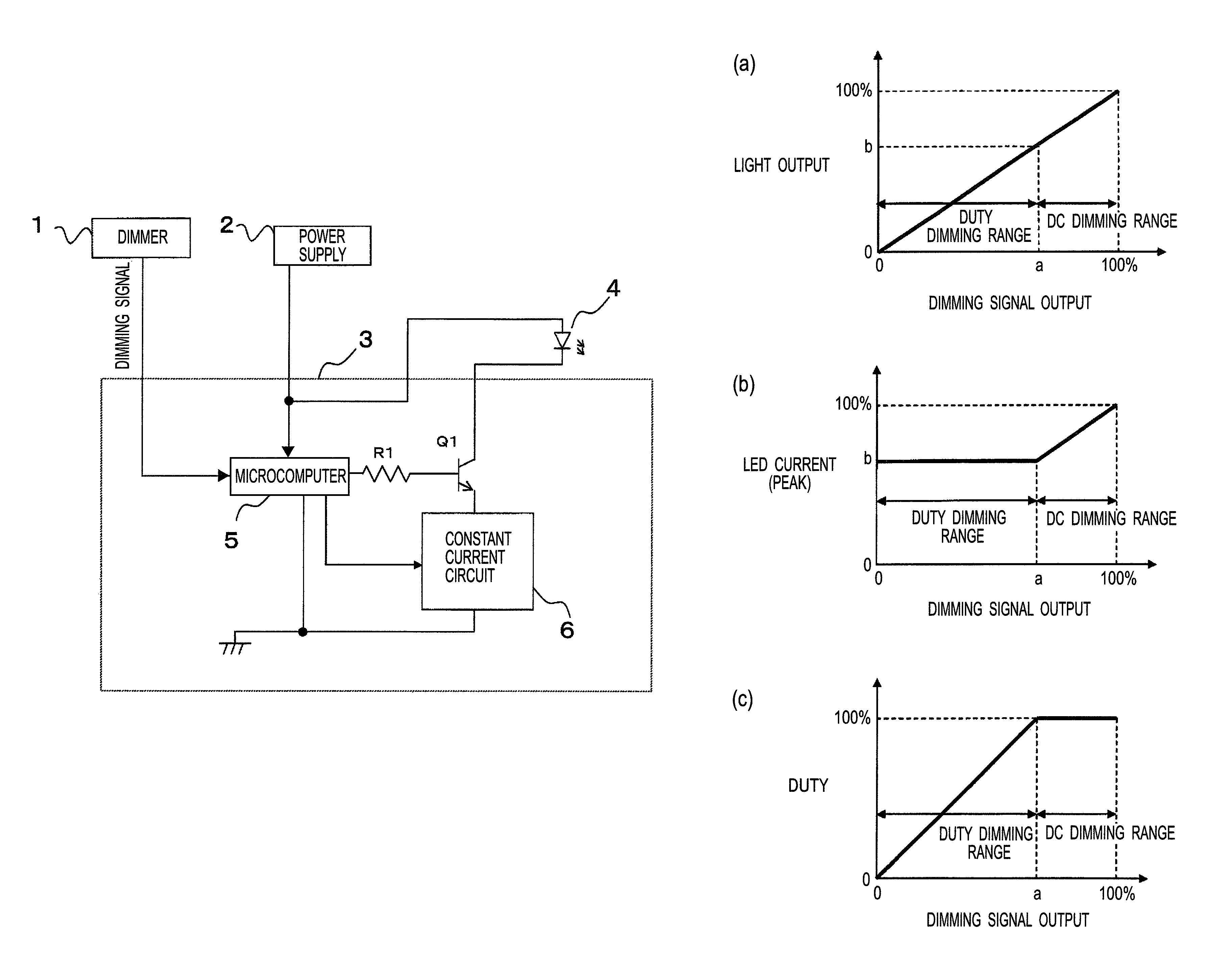
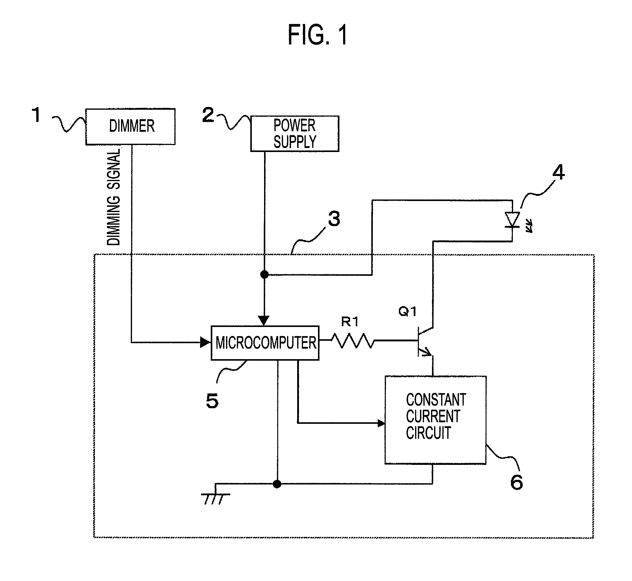
[0025]A circuit configuration of a first embodiment of the present invention is shown in FIG. 1. This embodiment is composed of: a dimmer 1, power supply 2; an LED lighting device 3; and an LED load 4. Moreover, the LED lighting device 3 is composed of: a microcomputer 5; a constant current circuit 6; a resistor R1; and a transistor Q1. The constant current circuit 6 is composed so as to flow therefrom a constant current designated by a signal from the microcomputer 5. The microcomputer 5 has functions to read a dimming signal from the dimmer 1, to control ON / OFF of the transistor Q1, and to set a current value of the constant current circuit 6.

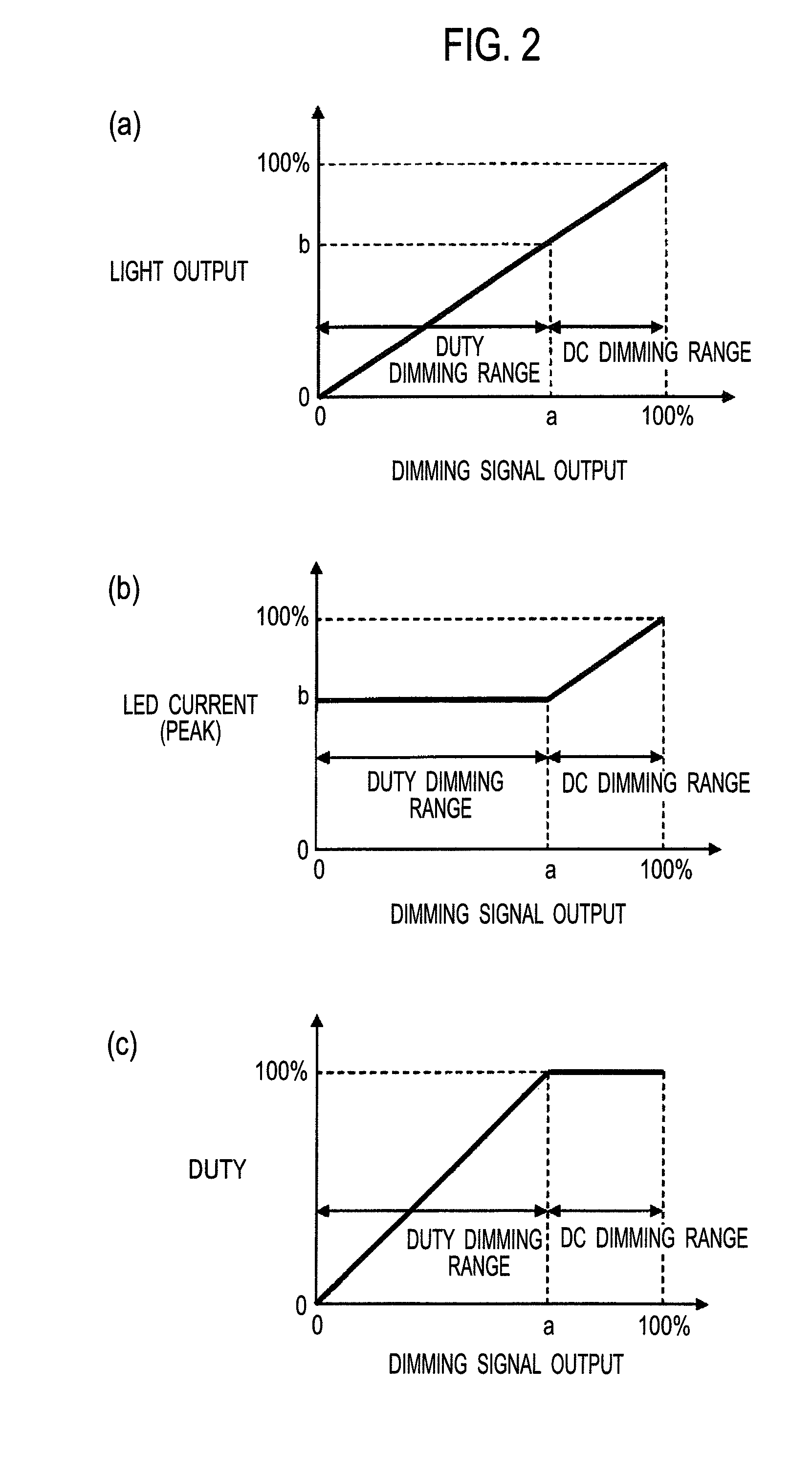
[0026]A predetermined dimming level (a) is stored in the microcomputer 5. In a range where a dimming degree is lower (where light is brighter), the microcomputer 5 fixes the transistor Q1 to be ON, and dims the light by changing a setting current of the constant current circuit 6. This refers to a DC dimming mode. In a range...

second embodiment

(Second Embodiment)

[0034]A circuit configuration of a second embodiment of the present invention is shown in FIG. 4. This embodiment is composed of: the dimmer 1; the power supply 2; the LED lighting device 3; and the LED load 4. Moreover, the LED lighting device 3 is composed of: the microcomputer 5; the constant current circuit 6; resistors R1 and R2; and a semiconductor switching element Q1 such as a MOSFET.

[0035]The constant current circuit 6 is composed so as to flow therefrom the designated constant current in accordance with a voltage signal from the microcomputer 5. The microcomputer 5 has functions to read the dimming signal from the dimmer 1, to control ON / OFF of the transistor Q1, and to set a current value of the constant current circuit 6. The dimming signal from the dimmer 1 is a DMX signal generally used in lighting. However, the DMX signal only has 256 levels (1 byte), and is insufficient for dimming the LED load 4. Hence, in order to make smooth light dimming in whi...

third embodiment

(Third Embodiment)

[0048]FIG. 8 is a circuit diagram showing an overall configuration of a third embodiment of the present invention. In this embodiment, a lighting circuit of the LED load 4 is composed of a flyback-type DC-DC converter 10 including two feedback control circuits 11 and 12. A description will be made below of a circuit configuration of the lighting circuit.

[0049]To alternating current input terminals 21 and 22 connected to a commercial power supply (AC 100 V, 50 / 60 Hz), an overvoltage protection element ZNR is connected in parallel, and alternating current input terminals of a diode bridge DB are connected. A smoothing capacitor C1 is connected in parallel to direct current output terminals of the diode bridge DB.

[0050]To the smoothing capacitor C1, a primary winding of an insulating transformer T1 is connected through output terminals Q and G of a drive circuit 14. The drive circuit 14 incorporates a power MOSFET (not shown) between the output terminals Q and G there...


PUM


Abstract

An LED dimming includes: current adjusting means (constant current circuit) for variably controlling a magnitude of a current flowing through an LED load; switching means (transistor) for intermittently controlling the current flowing through the LED load; and dimming controlling means (microcomputer) for controlling the current adjusting means and the switching means upon receiving a dimming signal outputted from a dimmer. In a case where the dimming signal outputted from the dimmer is on a higher brightness side than a predetermined level, the dimming controlling means flows a continuous current though the LED load, and dims the LED load based on a magnitude of the flowing current, and in a case where the dimming signal outputted from the dimmer is on a lower brightness side than the predetermined level, the dimming controlling means flows a pulse current through the LED load, and changes a mean value of waveforms of the pulse current, thereby dims the LED load. In this LED dimming apparatus, noise is less likely to occur even in a case where such an LED current is large, and brightness is less likely to vary even in a case where a dimming degree is increased.

Description

TECHNICAL FIELD[0001]The present invention relates to a light emitting diode (hereinafter, referred to as “LED”) dimming apparatus that uses an LED as a light source and has a dimming function.BACKGROUND ART[0002]As a conventional LED dimming apparatus, the one described in Patent Literature 1 (Japanese Patent Laid-Open Publication No. 2003-157986) has been known. This conventional LED dimming apparatus implements control for a voltage applied to an LED and switch dimming of the LED by a switching element that flows and interrupts an LED current in combination with each other. This LED dimming apparatus receives an external dimming signal by a control circuit. When a dimming degree that is based on the dimming signal is low (when emitted light is bright), the LED dimming apparatus constantly maintains the applied voltage to the LED, and dims the light by changing an ON / OFF duty ratio of the switching element. When the dimming degree that is based on the dimming signal is high (when ...

Claims


Application Information

Patent Timeline
Patent Type & Authority Patents(United States)
IPC IPC(8): H05B37/02H01L33/00H05B44/00
CPCH05B33/0851Y02B20/30H05B45/385H05B45/345H05B45/34H05B45/10H05B45/14
Inventor YAMASAKI, SHIGEAKISAKO, HIROYUKI
Owner PANASONIC CORP
Why Eureka
Try Eureka