Manufacturing method of an outer ring for a bearing unit

a technology of bearing unit and outer ring, which is applied in the direction of manufacturing tools, heat treatment equipment, furniture, etc., can solve the problems of unnecessarily large wheel-supporting bearing unit, adverse effect on traveling stability and braking performance of automobiles, and increase in weight, so as to achieve convenient manufacturing, improve the degree of freedom in designing the grinding tool, and achieve the effect of convenient operation

Inactive Publication Date: 2013-01-01
NSK LTD
View PDF18 Cites 4 Cited by
  • Summary
  • Abstract
  • Description
  • Claims
  • Application Information

AI Technical Summary

Benefits of technology

[0038]Further, according to the invention, even it the grinding tool and the high-frequency heating tool become slightly large in size, it becomes possible to allow the grinding tool and the high-frequency heating tool to enter the radially inner side of the outer ring for the bearing unit by the portion by which the grinding tool and the high-frequency heating tool are made to enter through the opening having a large opening area (the opening on the side close to the one outer ring raceway) in comparison with the case where they are made to enter through the opening having a small opening area (the opening on the side close to the other outer ring raceway). Accordingly, when the manufacturing method of the invention is carried out, it is possible to enlarge the degree of freedom in designing the grinding tool and the high-frequency heating tool used.
[0039]Furthers according to the invention, the operation of subjecting the both outer ring raceways to the grinding process (first aspect of the invention) or the operation of subjecting these both outer ring raceways to high-frequency heating (fifth aspect of the invention) can be performed simultaneously with respect to these both outer ring raceways. For this reason, these operations can be executed efficiently.
[0040]When carrying out the invention, if the manufacturing method shown in fourth aspect of the invention is adopted, the tendencies of occurrence of clogging or the tendencies of shedding of the both first and second working surfaces can be made mutually substantially equal. For this reason, it becomes possible to hardly occur a situation in which clogging or shedding occurs only in one of the both first and second working surfaces or a situation in which clogging occurs in either one working surface and shedding occurs in the other working surface. Accordingly, the setting of conditions when the pair of outer ring raceways are both subjected to grinding is facilitated.

Problems solved by technology

The inclination thus produced exerts an adverse effect on the traveling stability and braking performance of the automobile.
However, if both of these pitch circle diameters PCD1 and PCD2 are increased, the wheel-supporting bearing unit becomes unnecessarily large and the weight increases.
This result becomes contrary to the demand for compact size and lightweight, and is therefore undesirable.
However, if such a method is carried out, the operational efficiency deteriorates since the Labor of providing the grinding process for the both outer ring raceways 10a (10c) and 10b becomes cumbersome and complicated.

Method used


Image

  • Manufacturing method of an outer ring for a bearing unit
  • Manufacturing method of an outer ring for a bearing unit
  • Manufacturing method of an outer ring for a bearing unit

Examples


first embodiment

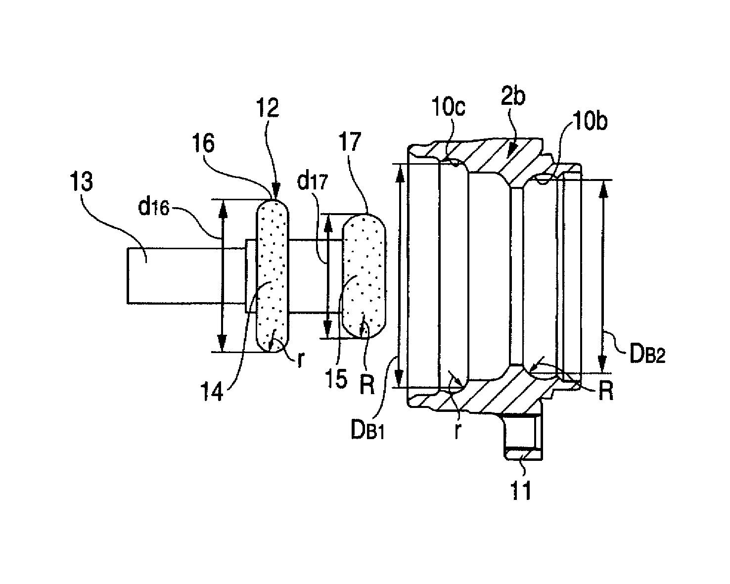
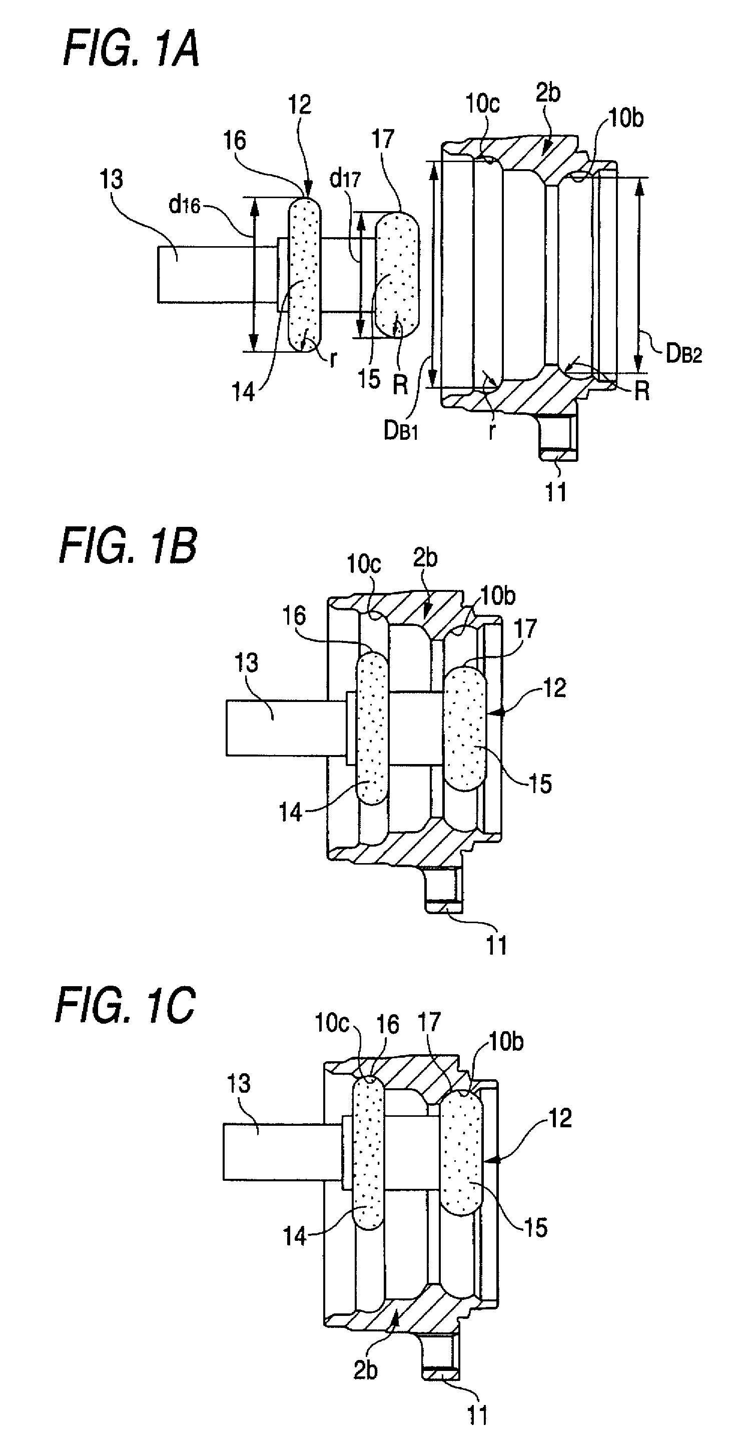
[0050]FIG. 1 shows a first embodiment of the invention corresponding to first and second aspects of the invention. An outer ring 2b to be manufactured is a component member of the wheel-supporting bearing unit shown in FIG. 6. Namely, this outer ring 2 has a first and a second outer ring raceway 10c and 10b formed in its inner peripheral surface and a coupling flange 11 formed on its outer peripheral surface for coupling to a suspension device. In addition, the diameter DB1 of the first outer ring raceway 10c is set to be greater than the diameter DB2 of the second outer ring raceway 10b (DB1>DB2) and the radius of curvature “r” of the cross-section profile of the first outer ring raceway 10c is set to be smaller than the radius of curvature “R” of the cross-section profile of the second outer ring raceway 10b (r

[0051]A grinding tool 12, which is used for subjecting the both outer ring raceways 10c and 10b to a grinding process, is formed such that a first grinding wheel 14 and ...

second embodiment

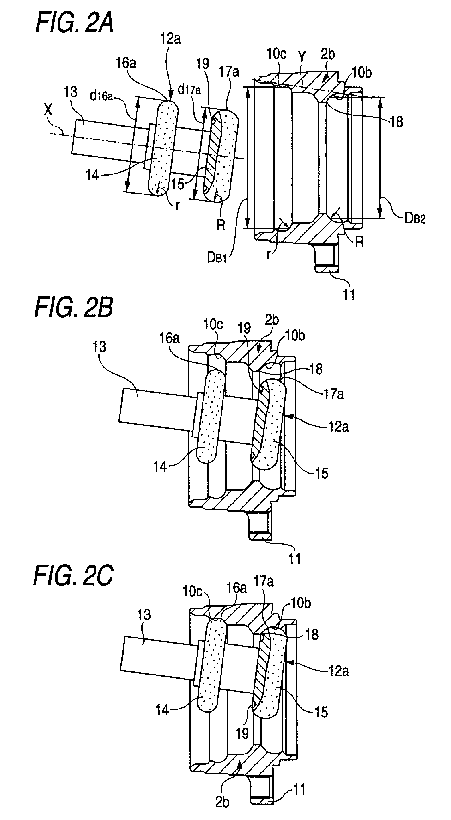
[0067]Next, FIG. 2 shows a second embodiment of the invention corresponding to first through third aspects of the invention. In this embodiment, an outside diameter d16a of a first working surface 16a and an outside diameter d17a of a second working surface 17a, which surfaces constitute a grinding tool 12a, are made mutually equal (d16a=d17a). In addition, the pitch between the both first and second working surfaces 16a and 17a with respect to the axial direction is defined such that the both first and second working surfaces 16a and 17a are simultaneously brought into registration and contact with the both first and second outer ring raceways 10c and 10b in a state in which a center axis of the grinding tool 12a is inclined with respect to the center axis of the outer ring 2b, as shown in FIG. 2(C) which will be referred to later.

[0068]In this embodiment, when the both first and second outer ring raceways 10c and 10b are subjected to the grinding process by using such a grinding t...

third embodiment

[0072]Next, FIG. 3 shows a third embodiment of the invention corresponding to fifth aspect of the invention. In this embodiment as well, the outer ring 2b to be manufactured is a component member of the wheel-supporting bearing unit shown in FIG. 6. Namely, this outer ring 2 has the first and the second outer ring raceway 10c and 10b formed in its inner peripheral surface and the coupling flange 11 formed on its outer peripheral surface for coupling to the suspension device. In addition, the diameter DB1 of the first outer ring raceway 10c is set to be greater than the diameter DB2 of the second outer ring raceway 10b (DB1>DB2) and the radius of curvature “r” of the cross-section profile of the first outer ring raceway 10c is set to be smaller than the radius of curvature “R” of the cross-section profile of the second outer ring raceway 10b (r

[0073]In addition, a high-frequency heating tool 20, which is used for subjecting the both outer ring raceways 10c and 10b to high-frequen...


PUM

PropertyMeasurementUnit
grain sizeaaaaaaaaaa
diameter d17aaaaaaaaaa

Abstract

With respect to an outer ring 2b in which a diameter DB1 of a first outer ring raceway 10c is greater than a diameter DB2 of a second outer ring raceway 10b (DB1>DB2), a method is realized which facilitates the entry of a grinding tool 12 into an inner side of the outer ring when these both outer ring raceways 10c and 10b are subjected to a grinding process.The grinding tool 12 is made to enter the inner side of the outer ring 2b through an opening on a side close to the first outer ring raceway 10c.

Description

TECHNICAL FIELD[0001]A manufacturing method of an outer ring for a bearing unit of the invention is used for manufacturing outer rings which make up various types of bearing units, such as a wheel-supporting bearing unit which is used for rotatably supporting an automotive wheel to a suspension device.BACKGROUND ART[0002]A wheel of an automobile and a rotating member in a brake system are rotatably supported to a suspension device via a wheel-supporting bearing unit. FIG. 4 shows an example of a conventionally known wheel-supporting bearing unit. This wheel-supporting bearing unit includes a hub 1, an outer ring 2, and a plurality of balls 3 which are rolling elements. The hub 1 is formed by combining together a hub body 4 and an inner ring 5.[0003]The hub body 4 has a mounting flange 6 disposed on a portion near to an outer end of an outer peripheral surface of the hub body 4 and adapted to support the automotive wheel and the rotating member for brake system; a first inner ring ra...

Claims


Application Information

Patent Timeline
Patent Type & Authority Patents(United States)
IPC IPC(8): B21D53/10
CPCB24B5/06B24B19/06C21D1/10C21D9/40F16C33/64F16C19/186Y10T29/49643F16C2240/80F16C2326/02Y10T29/49689Y02P10/25
Inventor TSUKAMOTO, SHIGEMIKAWAMURA, KATSUYUKIISHIDA, HIROHIDEWAKABAYASHI, TATSUO
Owner NSK LTD
Why Eureka
Try Eureka