Purification system for variable post injection in LP EGR and control method for the same

a technology of variable post injection and purification system, which is applied in the direction of electrical control, machines/engines, mechanical equipment, etc., can solve the problems of affecting the efficiency of lnt and dpf regeneration, the timing of fuel injection may be delayed, and the amount of pm caused by regeneration of lnt is not known, so as to achieve the effect of enhancing fuel efficiency and reducing air pollution

Inactive Publication Date: 2013-01-01
HYUNDAI MOTOR CO LTD +1
View PDF19 Cites 8 Cited by
  • Summary
  • Abstract
  • Description
  • Claims
  • Application Information

AI Technical Summary

Benefits of technology

[0030]The purification system for variable post injection in LP EGR and control method for the same according to an exemplary embodiment of the present invention may reduce NOx generation in the LP EGR, and precisely control regeneration of the NOx storage catalyst according to generation of the EGR gas and NOx, the engine operation conditions and so on so that air pollution material can be reduced and also fuel efficiency can be enhanced.

Problems solved by technology

For example, fuel injection timing may be delayed.
Regarding the simultaneous NOx-PM reduction apparatus, it is believed that simultaneous generation of the LNT and DPF is not possible.
In addition, the regeneration of LNT is required to be performed in a rich range of an air / fuel ratio, and thus the regeneration of the LNT causes a substantial amount of PM.
However, apparatus and / or algorithm for a regeneration control of the trapped PM by an after-burning thereof have not sufficiently investigated.
Consequently, in the state of the art, durability of the DPF is still problematic since an excessive heat may be produced during the regeneration of the filter thereby causing a damage of the DPF.
Therefore, in this case, a PM trapping limit of a catalyst support of the DPF easily becomes saturated, and this may be a cause of the damage of the support of the DPF during an active regeneration of the DPF.

Method used


Image

  • Purification system for variable post injection in LP EGR and control method for the same
  • Purification system for variable post injection in LP EGR and control method for the same
  • Purification system for variable post injection in LP EGR and control method for the same

Examples


Embodiment Construction

[0038]Reference will now be made in detail to various embodiments of the present invention(s), examples of which are illustrated in the accompanying drawings and described below. While the invention(s) will be described in conjunction with exemplary embodiments, it will be understood that present description is not intended to limit the invention(s) to those exemplary embodiments. On the contrary, the invention(s) is / are intended to cover not only the exemplary embodiments, but also various alternatives, modifications, equivalents and other embodiments, which may be included within the spirit and scope of the invention as defined by the appended claims.

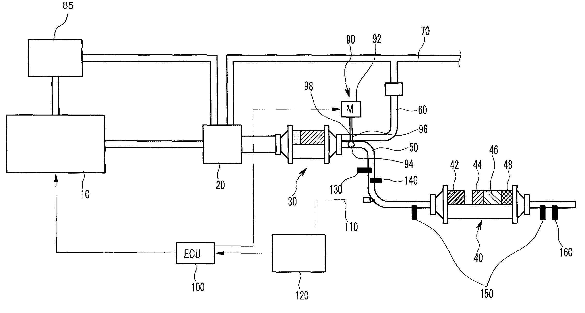
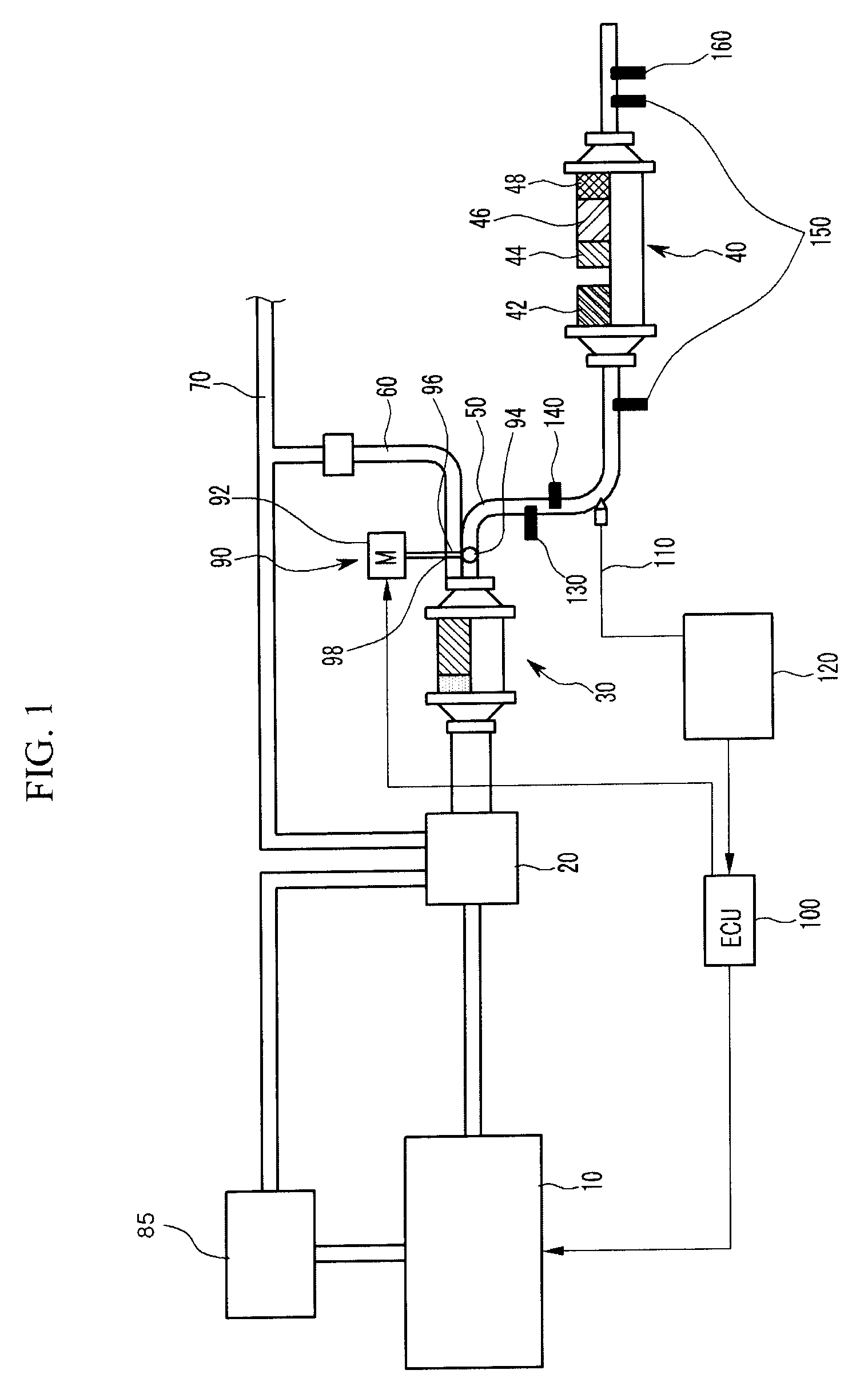
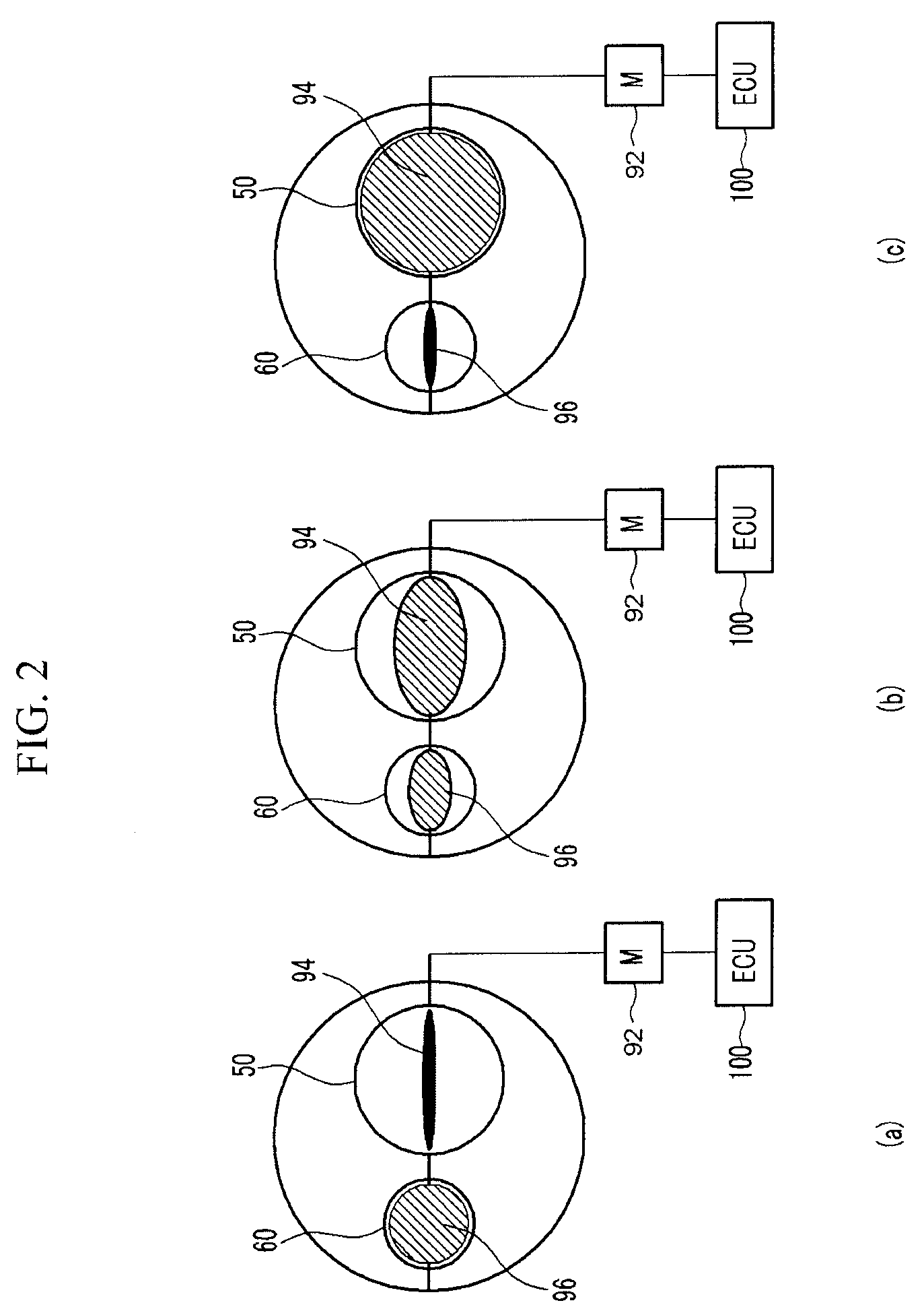
[0039]FIG. 1 is a schematic diagram of a purification system for variable post injection in LP EGR and FIG. 2 is a drawing showing an exhaust gas control portion of a purification system for variable post injection in LP EGR according to various embodiments of the present invention.

[0040]Referring to FIG. 1 and FIG. 2, a purification ...


PUM


Abstract

A purification system for variable post injection in LP EGR, the system includes a turbo charger disposed downstream of a diesel engine, a DPF (catalyzed particulate filter) disposed downstream of the turbo charger, a NOx reduction apparatus disposed upstream or downstream of the DPF, a bypass line diverged from the DPF for mixing exhaust gas and air inflowing the turbo charger, a exhaust gas control portion disposed downstream of the DPF for controlling flowing of the exhaust gas and a lean / rich controlling portion for controlling lean / rich of the exhaust gas.

Description

CROSS-REFERENCE TO RELATED APPLICATION[0001]The present application claims priority to Korean Patent Application Number 10-2008-0120064 filed on Nov. 28, 2008, the entire contents of which application is incorporated herein for all purposes by this reference.BACKGROUND OF THE INVENTION[0002]1. Field of the Invention[0003]The present invention relates to purification of an exhaust gas of a diesel engine vehicle. More particularly, the present invention relates to a purification system for variable post injection in LP EGR and the control method for the same.[0004]2. Description of Related Art[0005]Nitrogen oxides (NOx) and particulate matters (PM) are principal air pollution material of a diesel engine vehicle. Therefore, they are under strict emission regulation of a diesel engine.[0006]Several technologies have been developed to cope with the emission regulation of the diesel engine. For example, fuel injection timing may be delayed. In addition, exhaust gas recirculation (EGR) has...

Claims


Application Information

Patent Timeline
Patent Type & Authority Patents(United States)
IPC IPC(8): F01N5/04F01N1/00
CPCF01N3/033F01N13/009F01N3/0814F01N3/106F01N3/206F01N11/002F02M25/0709F02M25/0718F02M25/0719F02M25/0796F01N3/00F01N13/0093F01N3/0807F01N2240/30F01N2240/36F01N2610/03F01N2610/05F01N2900/1824Y02T10/121Y02T10/47Y02T10/24F02M26/06F02M26/15F02M26/16F02M26/71Y02T10/12Y02T10/40F02D43/00F02D45/00
Inventor LEE, JIN HA
Owner HYUNDAI MOTOR CO LTD
Why Eureka
Try Eureka