Advanced airship technologies

a technology of advanced airships and airframes, applied in the field of airships, can solve the problems of large unsteady wake, high drag, and increase the complexity of the solution

Inactive Publication Date: 2013-01-01
DANCILA
View PDF14 Cites 36 Cited by
  • Summary
  • Abstract
  • Description
  • Claims
  • Application Information

AI Technical Summary

Problems solved by technology

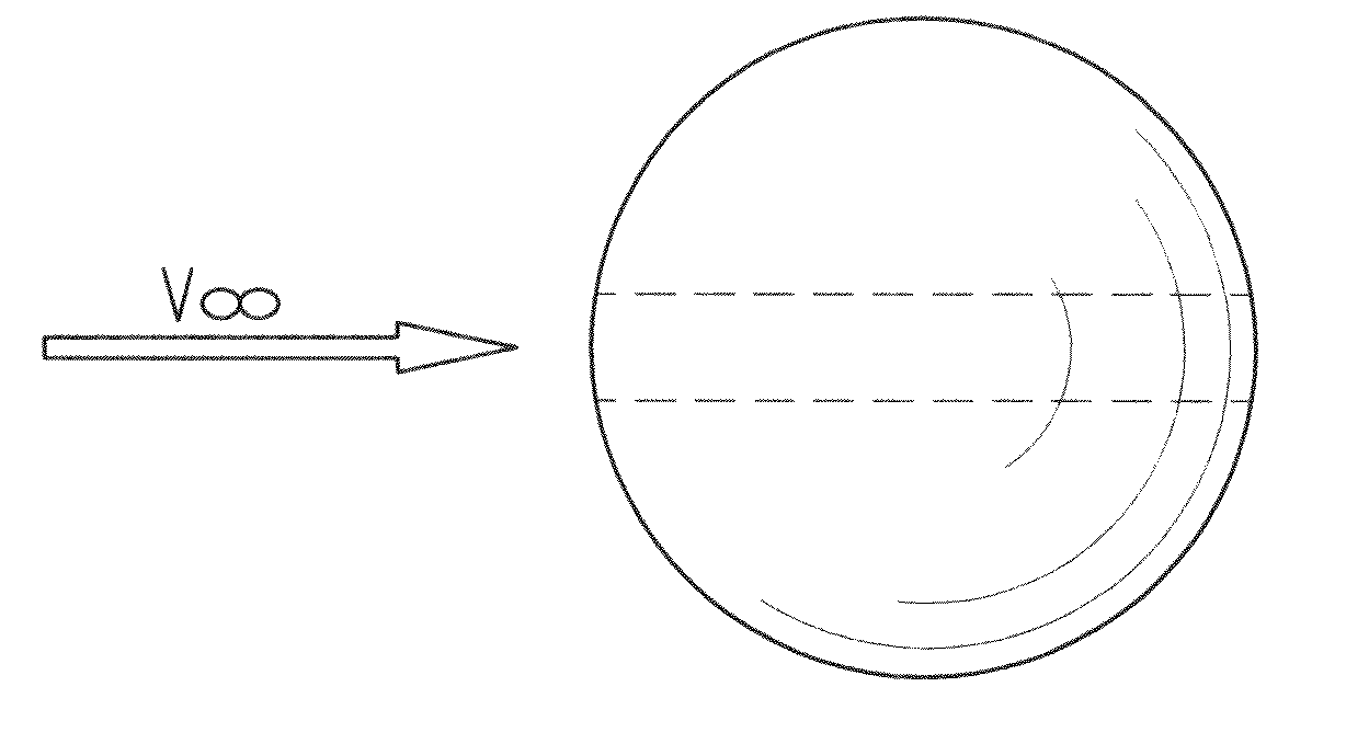
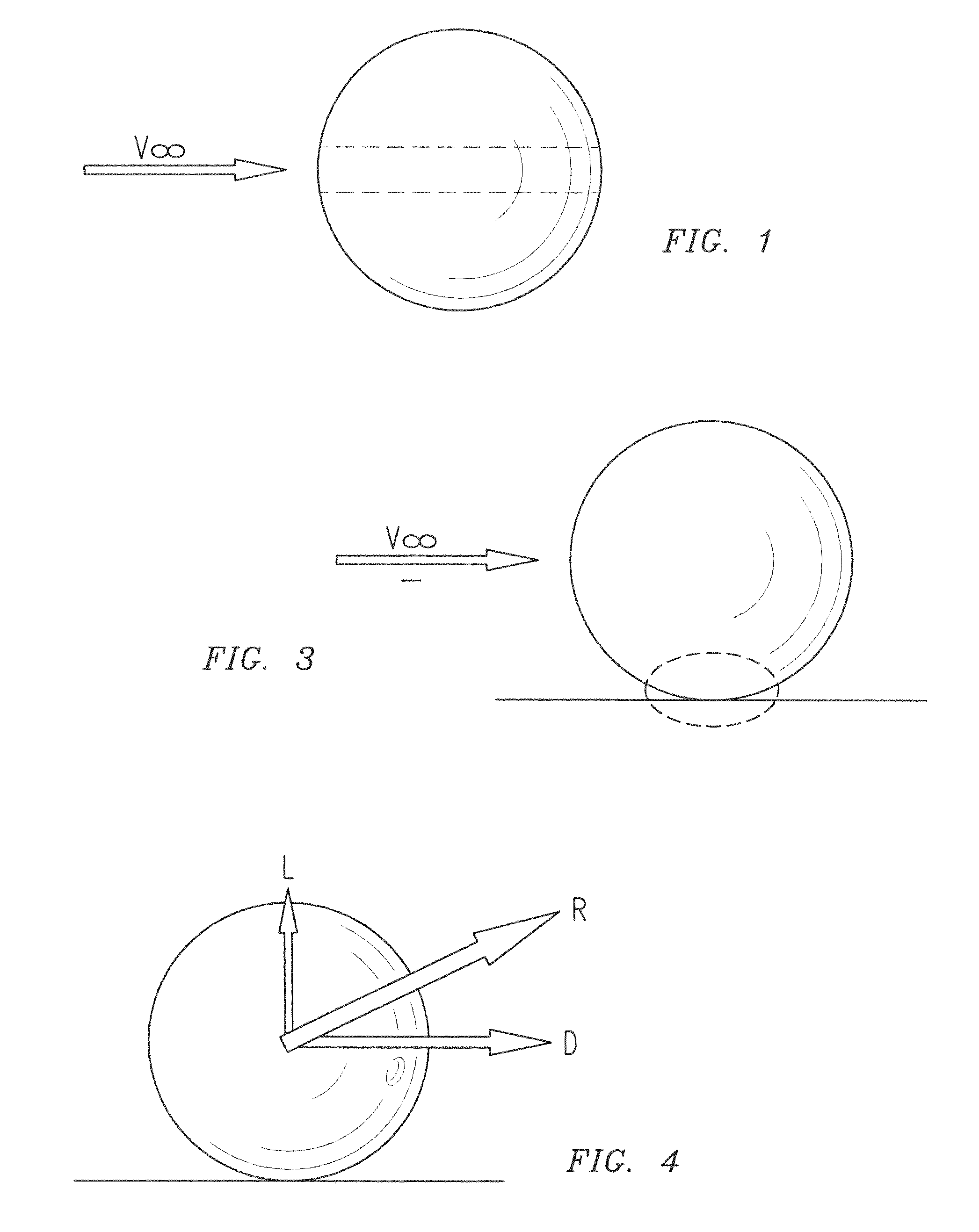
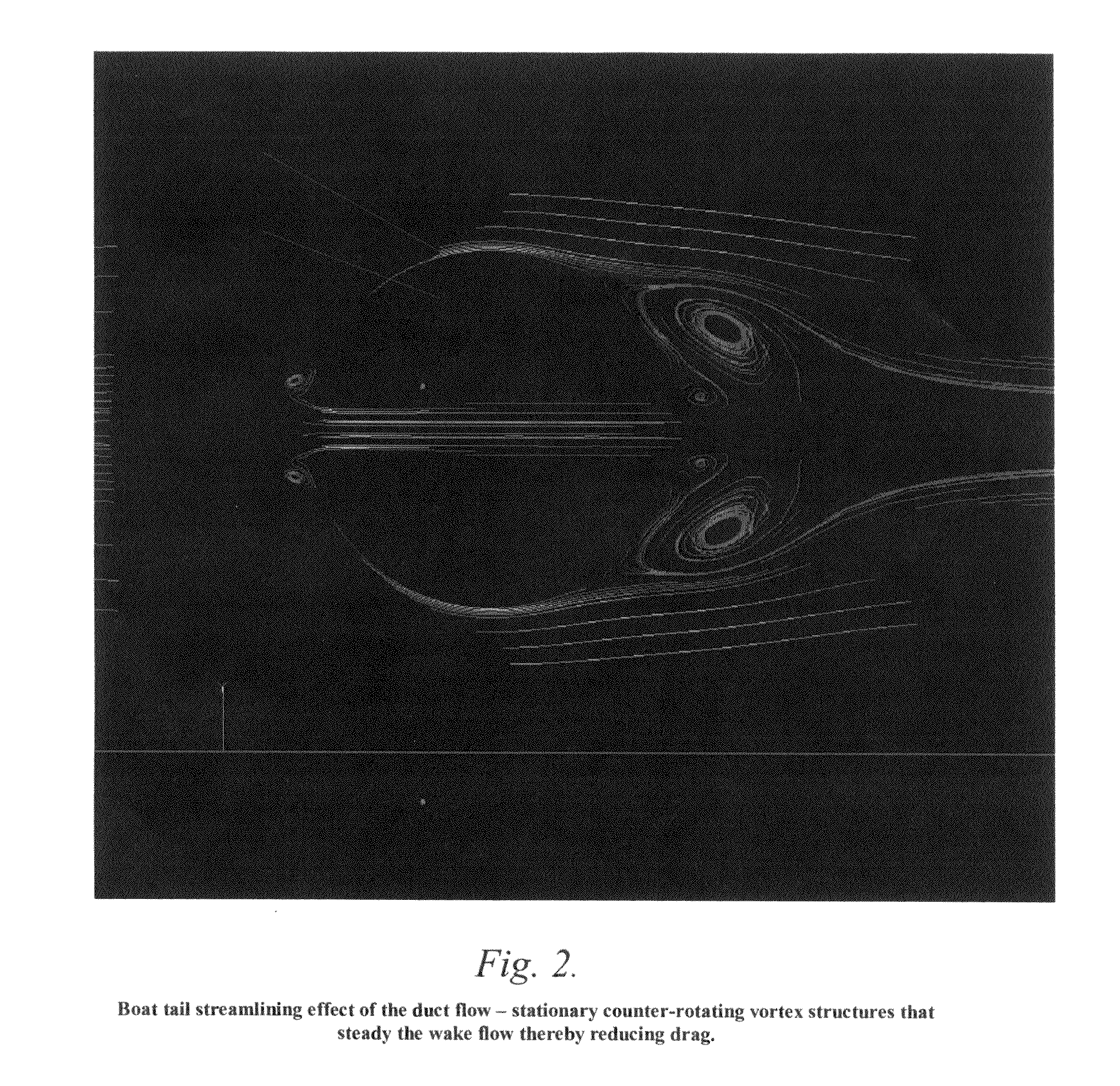
The high drag coefficients are caused by early separation of a boundary layer, resulting in a large unsteady wake that is dominated by large eddies and low average pressure.
Research has shown that the unsteadiness of the wake is responsible for large amounts of kinetic energy being continually shed in the wake (von Karman1, Roshko2), which causes high drag.
However, the external provision of fluid for base bleed is energetically expensive and it increases the level of complexity of the solution.
In the case of a body that is moored to the ground such an increase in airloads requires corresponding increases in mooring loads, which is undesirable.
However, a simple inspection of classical airship shapes shows this not to be the case for at least the reasons that (1) Low aspect ratio, and in the limit spherical hulls are bluff bodies characterized by high drag; and (2) Low aspect ratio hulls are aerodynamically unstable, having a tendency to broadside.
However, while characterized by lower drag and lower level of aerodynamic instability they are nevertheless affected by deficiencies of their own, which include the following:Weight penalty associated with much larger envelope area;Additional weight penalty due to increased envelope material strength requirements due to increased structural loads on the elongated airship hull;Limited turn performance, resulting in large airship turn radii;Large required ground footprint for mooring in order to allow an airship moored by the nose of the hull to freely weathervane with the wind;Lifting gas sloshing instability at low fill factors, which can cause the airship hull to uncontrollably reach a fully nose up or fully tail up attitude.

Method used


Image

  • Advanced airship technologies
  • Advanced airship technologies
  • Advanced airship technologies

Examples


example

[0081]An implementation of the present invention on a small scale (6.5 ft diameter) remote controlled experimental airship model is shown in FIGS. 17-18. This is a fully electric vehicle, with Li polymer batteries and a brushless electric motor controlled by an electronic speed control unit connected to a remote control receiver driving a propeller within the duct of the airship. The receiver also controls the servomechanisms that actuate control surfaces located at the exit end of the duct. Gyrostabilization units are connected in series with each of the servomechanisms in order to provide flight stability in pitch and yaw. Details of the specific implementation of the duct end control surfaces are shown in FIG. 19. Details of the specific implementation of the duct propulsor, in this case a propeller, are shown in FIG. 20. FIGS. 17 and 18 illustrate the ducted spherical airship of the present invention with a propeller-based propulsor inside the duct and louver-based control surfa...


PUM


Abstract

An airship is disclosed in the form of a spherical hull having a venting duct extending diagonally therethrough from an entrance end at the forward facing surface of the hull to an exit end at the rearward facing surface of the hull. A propeller is disposed in the duct to direct an air flow through the duct for expulsion at the exit end and the exiting flow is vectored by a set of controllable louvers at the exit end. The expulsed airflow reduces drag normally associated with a spherical airship by disturbing the wake at the trailing surface of the airship. A mooring method and apparatus also is disclosed for minimizing wind induced loads on the airship, or indeed on any body such as a gas storage tank, by supporting the airship or other body a predetermined distance above the ground.

Description

REFERENCE TO RELATED APPLICATIONS[0001]The benefit of the filing dates of U.S. provisional patent application Ser. Nos. 60 / 938,118 filed May 15, 2007 and 60 / 938,186 filed May 16, 2007 is hereby claimed.TECHNICAL FIELD[0002]This invention generally relates to airships and their operation. More specifically, the invention relates to drag reduction on airship hulls using a ducted hull configuration that optionally includes propulsion means forcing airflow through the duct. Airship control means may be associated with the duct flow. This invention also more specifically relates to an apparatus and method for mooring an airship hull in such a way as to reduce wind-induced airloads.BACKGROUNDBluff Body Drag Reduction Via Venting[0003]Bluff bodies, such as spheres, are generally characterized by high drag coefficients when exposed to an airflow. The high drag coefficients are caused by early separation of a boundary layer, resulting in a large unsteady wake that is dominated by large eddie...

Claims


Application Information

Patent Timeline
Patent Type & Authority Patents(United States)
IPC IPC(8): B64B1/00
CPCB64B1/26B64B1/30B64B1/62B64B1/66
Inventor DANCILA, DRAGOS-STEFAN
Owner DANCILA
Why Eureka
Try Eureka