Powder particle shaping device and method

a technology of powder particle and shaping device, which is applied in the field of powder particle morphological control, can solve the problems of uncertainty, difficult to achieve expected effect and efficiency, and insufficient processing strength, and achieve the control of processing intensity, high processing controllability, and improved processing efficiency.

Active Publication Date: 2013-01-01
HU XINYU +1
View PDF9 Cites 47 Cited by
  • Summary
  • Abstract
  • Description
  • Claims
  • Application Information

AI Technical Summary

Benefits of technology

[0016]According to the device and method of the present application, combined actions of several pistons or similar piston assemblies forming the closed cavity are caused through the change of the shape of the closed cavity, and typically by controlling the external forces, so that the powder particles with which the cavity is filled full are compressed, and the cavity space and relative positions of the powder particles therein change. As the processed material is closed in the cavity and cannot be released, the powder particles are compressed in all directions, and sheared, and thus mutual friction occurs between particles, thereby removing edge angles and burrs from the surfaces of the particles, achieving the purpose of pulverizing, shaping, or spheroidizing the powder particles, and realizing the morphological control of the powder particles in the cavity.
[0017]Different from the conventional “cold processing” with high-speed impact and shearing, the present application can maintain the original property of the processed material, while the disadvantages of other powder processing manners such as rolling, ball milling, and vibration grinding are well overcome, so as to improve the control on factors affecting the processing effect, and especially the controllability of the processing intensity. In processing of the powder particles, there is no situation of “open” or “partial open”, and the pressure or impact force is persistently maintained at a stable and effective level.
[0018]Compared with the conventional solution, the present application has high processing controllability, well adapts to the processed objectives (in respect of the particle size and hardness), and saves space, improves the efficiency, and reduces noise pollution and energy consumption. In addition, the material of the device useful in the present application can be widely selected and is economical, and automatic mass production can be achieved while the given processing objective is achieved. The present application is a preferred choice for shaping or spheroidizing the powder particles, and also can effectively realize forced pulverization and deep grinding of the powder.

Problems solved by technology

The compacting, rolling, vibration grinding, and ball milling all have disadvantage that the mixture of the processed powder and the grinding media partially contacts air in an effective processing stage, that is, there is “open” or “partial open” situation.
For the relatively “soft” or “hard” powder particles, the absolute strength for processing is limited, and the expected effect and efficiency aredifficult to be achieved.
In addition, non-cyclic ball milling and vibration grindingboth have the problem of separation of the milling balls from the ground powder, andthe processing strength varies with the increasing abrasion of the grinding balls, thisincurs uncertainty to the processing process.
Moreover, the problems of noise andwaste of energy for driving the equipment and the grinding balls to vibrate or rotateare difficult to overcome.
Among the disadvantages, the most serious is the limitedcontrollability of the processing intensity.

Method used


Image

  • Powder particle shaping device and method
  • Powder particle shaping device and method
  • Powder particle shaping device and method

Examples


Embodiment Construction

[0031]The present application is further described in detail with reference to embodiments and accompanying drawings.

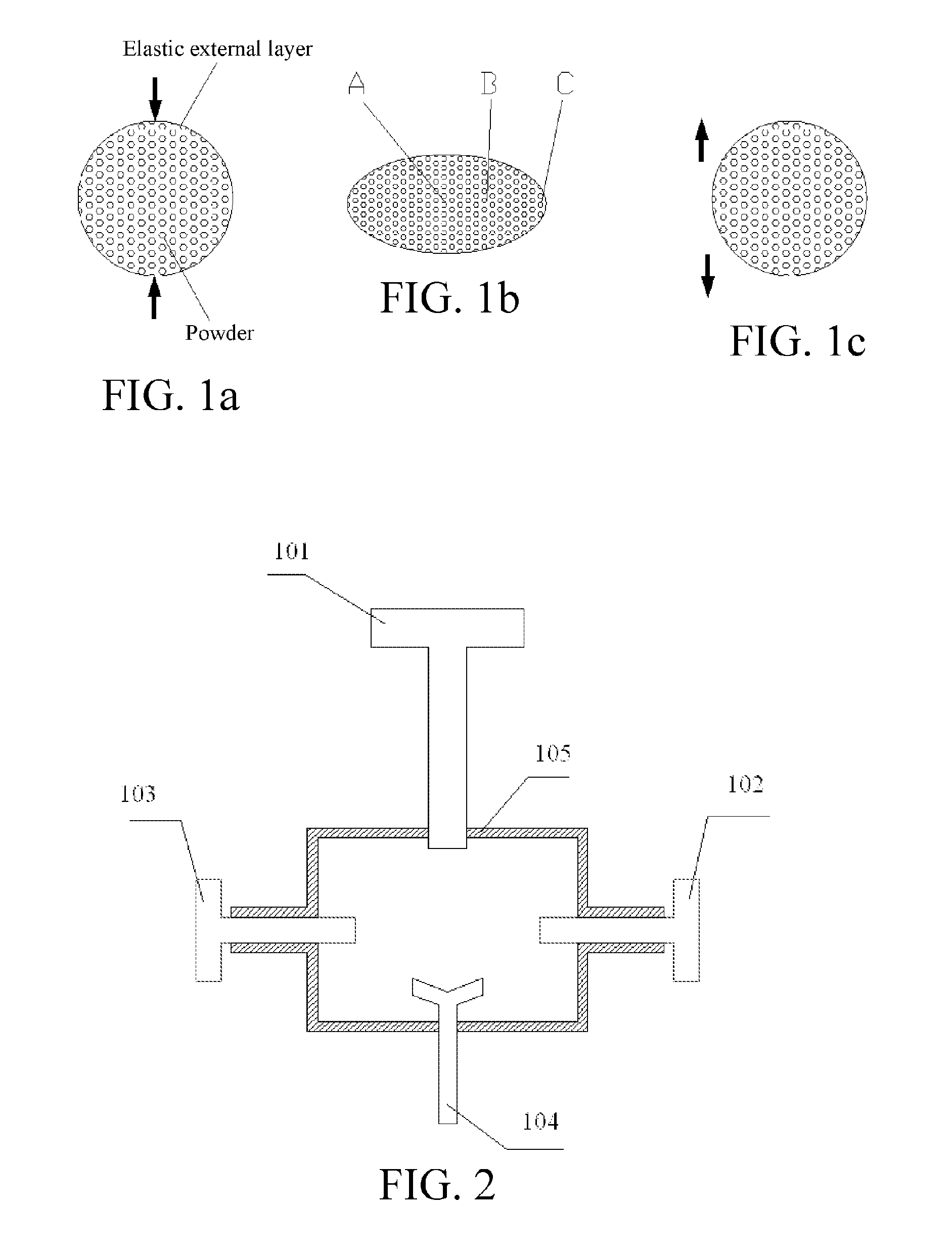
[0032]As shown in FIGS. 1a-1c, an embodiment shows basic principles of the present application.

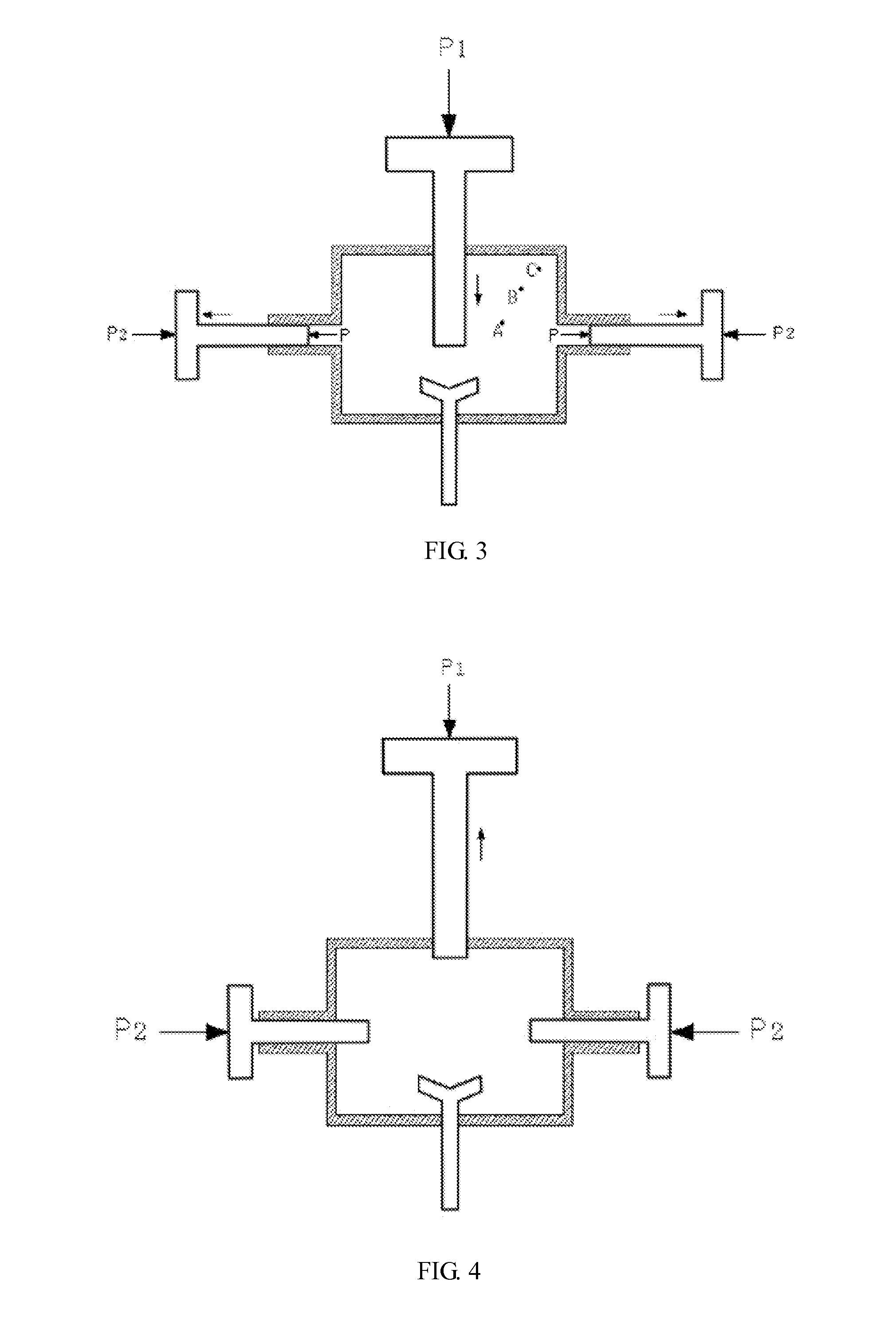
[0033]As shown in FIG. 1a, a powder particle shaping device uses a closed ideal elastic cavity, and the powder particles are enclosed in the elastic cavity. In an initial state, the powder particles are only compressed by an enclosure force. The same pressure is applied at a top and a bottom of the cavity, the elastic cavity deforms horizontally (or even expands), and changes from a spherical shape to an ellipsoidal shape as shown in FIG. 1b. As shown in FIG. 1c, when the external force is released, the elastic cavity is restored to an original shape.

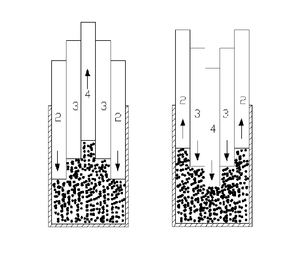
[0034]In the cycle, the powder particles at different positions in the cavity are compressed in multiple directions; at the same time, due to the cavity deformity (or plus the volume change), relative movements, and thus frictio...


PUM

PropertyMeasurementUnit
spherical shapeaaaaaaaaaa
ellipsoidal shapeaaaaaaaaaa
pressureaaaaaaaaaa

Abstract

A powder particle shaping device includes a closed cavity capable of changing between multiple shapes as an external pressure changes, and the closed cavity compresses and moves powder particles with which the closed cavity is filled full while the shape changes. A powder particle shaping method is further provided, which includes a. filling a cavity full with powder particles to be shaped; and b. applying a varying external pressure to make the cavity change repeatedly between multiple shapes, thereby making the powder particles under compression move and be subject to friction, where the cavity is kept in a closed state during an effective processing process. The shaping device and method have highly controllable shaping processing intensity of powder particles and stable processing strength, and thus are applicable to shaping and pulverization of various powder particles, and also applicable to pulverization and further shaping processing of dispersed agglomerates.

Description

CROSS REFERENCE TO RELATED APPLICATIONS[0001]This application is a continuation of PCT / CN2010 / 076119, filed on Aug. 18, 2010. The contents of PCT / CN2010 / 076119 are all hereby incorporated by reference.BACKGROUND[0002]1. Technical Field[0003]The present application relates to morphological control of powder particles, and more particularly to a powder particle shaping device and method.[0004]2. Related Art[0005]Morphological control of powder particles, being one content of powder engineering, is processing of external surface of powder particles with an intended objective, to achieve a special individual or overall function of the powder particles. Relatively spheroidized powder particles can improve the tap density, filling density, and fluidity of the powder, for example, the spheroidization of cement powder particles can improve the performance of cement, the spheroidization of metal ink particles can increase the light reflection degree, and improve the print quality, and the sp...

Claims


Application Information

Patent Timeline
Patent Type & Authority Patents(United States)
IPC IPC(8): B29B9/16
CPCB22F9/04B22F2999/00B22F2009/045B22F3/003B30B11/02
Inventor HU, XINYUHU, XIJUN
Owner HU XINYU
Why Eureka
Try Eureka